R&S OSP Instrument Functions
Operating Manual 1505.3896.12 - 14 91
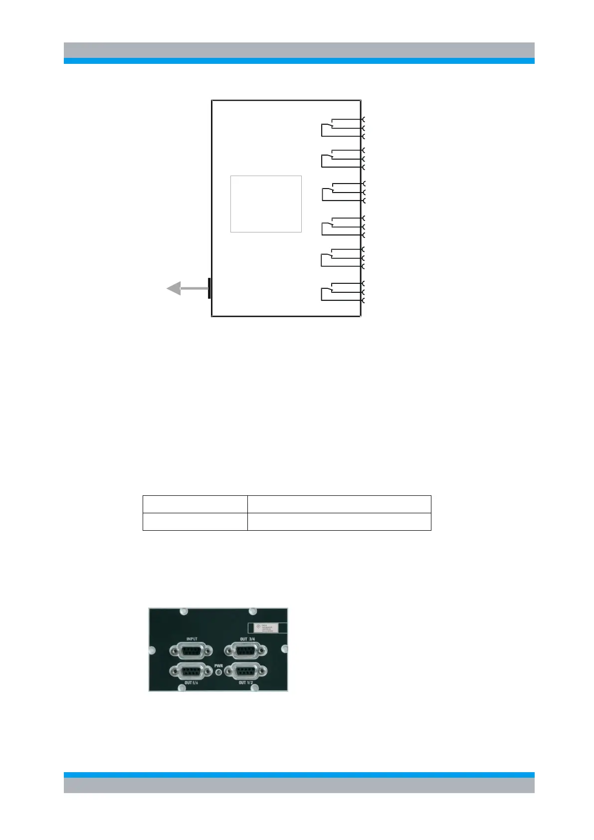
Interface logic
Relay drivers
I
2
C memory
Module OSP-B106
Interface
connector
To OSP frame
(cable W5 or 6 or 7
NO
NC
C
NO
NC
C
NO
NC
C
NO
NC
C
NO
NC
C
NO
NC
C
K1
K2
K3
K4
K5
K6
Figure 5-22: Block Diagram Module R&S OSP-B106
When the module R&S OSP-B106 is configured within the R&S OSP, a manual operation
of the module can be performed via the OSP Panel. See chapter 3.3.6 for details.
For remote control operation see chapters 6 and 7.
See chapter 9.2.6 for details on the connector pin assignments.
The module OSP-B106 has a double width. Therefore only one module can be
installed in one R&S OSP frame. If more than one module is required, the extension
unit R&S OSP150 must be used. For further information on the extension unit
R&S OSP150 see chapter 8.2.
The description above applies to further options of the R&S OSP as far as the option
has got a similar relay configuration. It will apply to the following modules:
6 x SPDT relay with N-Connectors, 12 GHz
5.2.6 DC MUX Module R&S OSP-B108
The module R&S OSP-B108 is a four pole one to six multiplexer for DC.
It is controlled equivalent to first Relay K11 of R&S OSP-B102.
Figure 5-23: Module R&S OSP-B108
The R&S OSP-B108 module is supplied with power and controlled from the R&S OSP
via a single connector on the R&S OSP-B108 printed circuit board.

 Loading...