Home
Ricoh
All in One Printer
AFICIO MP C305SP
Ricoh AFICIO MP C305SP Field Service Manual
4
of 1
of 1 rating
1550 pages
Give review
Manual
Specs
To Next Page
To Next Page
To Previous Page
To Previous Page
Loading...
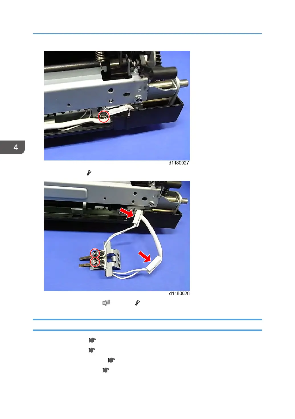
2.
Thermistor holder (
x 1)
3.
Pressure roller thermistors (
x 1 each,
x 1 each)
Pressure Roller
1.
Fusing upper cover (
p.245)
2.
Fusing lower cover (
p.245)
3.
Fusing entrance guide plate (
p.246)
4.
Pressure roller thermistors (
p.247)
4. Replacement and Adjustment
248
249
251
Table of Contents
Table of Contents
13
Important Safety Notices
3
Responsibilities of the Customer Engineer
3
Customer Engineer
3
Reference Material for Maintenance
3
Before Installation, Maintenance
3
Shipping and Moving the Machine
3
The Aim of Anti-Tip Components and Precautions
3
Power
4
Installation, Disassembly, and Adjustments
4
Special Tools
4
During Maintenance
5
General
5
Safety Devices
5
Organic Cleaners
5
Lithium Batteries
6
Power Plug and Power Cord
6
After Installation, Servicing
7
Disposal of Used Items
7
Points to Confirm with Operators
7
Special Safety Instructions for Toner
8
Accidental Physical Exposure
8
Handling and Storing Toner
8
Toner Disposal
9
Safety Instructions for this Machine
9
Prevention of Physical Injury
9
Health Safety Conditions
10
Observance of Electrical Safety Standards
10
Safety and Ecological Notes for Disposal
10
Laser Safety
10
Symbols, Abbreviations and Trademarks
12
Trademarks
12
Table of Contents
13
Product Information
27
Specifications
27
Machine Configuration
28
Main Unit
28
Controller Options
29
Overview
31
Component Layout
31
Paper Path
33
With All Options
33
Drive Layout
34
Installation
35
Installation Requirements
35
Environment
35
Machine Level
36
Machine Space Requirements
36
Machine Dimensions
37
Power Requirements
37
Mainframe Installation
39
Installation Flow Chart
39
Accessory Check
40
Component List
40
Installation Procedure
41
Tapes, Retainers and Toner Bottles
41
Paper Tray
47
Decals
48
Settings Relevant to the Service Contract
48
Settings for @Remote Service
49
Language Selection
52
Registration of Languages Other than the Defaults
54
Fax Icon Addition
54
External USB Keyboard (External Option)
57
Transporting the Machine
59
Instructions for the Customers
59
Paper Feed Unit (D573)
60
Component Check
60
Installation Procedure
60
1-Bin Tray Unit (D574)
63
Components Check
63
Installation Procedure
64
Platen Cover (D607)
72
Component Check
72
Installation Procedure
72
Ardf (D606)
76
Accessory Check
76
Installation Procedure
76
Copy Data Security Unit (D640)
80
Component Check List
80
Installation
80
User Tool Setting
82
Optional Counter Interface Unit Type a (B870)
84
Component Check
84
Installation Procedure
85
Mechanical Counter Installation (Only for NA)
87
Installation Procedure
88
HDD Option Type C305 (D656)
90
Component Check
90
Installation Procedure
91
HDD Encryption
95
Data Overwrite Security
96
Key Counter Bracket Type H (A674)
98
Component Check
98
Installation Procedure
99
Anti-Condensation Heater (Mainframe)
103
Component Check
103
Installation Procedure
103
Anti-Condensation Heater (Optional Unit)
110
Component Check
110
Installation Procedure
111
For Installing the Tray Heater in D573
112
For Joining the Mainframe with the Optional Paper Feed Unit
116
Joining Two Optional Paper Feed Units
120
IC Card Reader (External Option)
122
Component Check
122
Installation Procedure
123
When Installing in a Machine that Does Not Have the 1-Bin Tray Unit
123
When Installing in a Machine that Has a 1-Bin Tray Unit
125
Controller Options
129
Overview
129
I/F Card Slots
129
SD Card Slots
130
USB Connectors
130
SD Card Appli Move
130
Overview
130
Move Exec
132
Undo Exec
133
File Format Converter Type E
134
IEEE 1284 Interface Board Type a
136
Installation Procedure
136
IEEE 802.11A/G, G Interface Unit Type J/K
137
Installation Procedure
137
UP Mode Settings for Wireless LAN
140
SP Mode and up Mode Settings for IEEE 802.11A/G, G Wireless LAN
141
Bluetooth Interface Unit Type D
142
VM Card Type T
143
Camera Direct Print Card Type K
144
SD Card for Netware Printing Type J
146
Browser Unit Type H
147
Installation Procedure
147
Browser Icon Addition
149
Gigabit Ethernet Board Type a
151
Check All Connections
153
Preventive Maintenance
155
Maintenance Tables
155
PM Parts Settings
156
Before Removing the Old PM Parts or Yield Parts
156
After Installing the New PM Parts
156
Preparation before Operation Check
156
Operation Check
157
Replacement and Adjustment
159
Beforehand
159
Special Tools
160
Image Adjustment
161
Scanning
161
Scanner Sub-Scan Magnification
161
Scanner Leading Edge and Side-To-Side Registration
162
Ardf
162
ARDF Side-To-Side, Leading Edge Registration and Trailing Edge
162
ARDF Sub-Scan Magnification
163
Registration
163
Image Area
163
Leading Edge
163
Side to Side
164
Adjustment Standard
164
Paper Registration Standard
164
Adjustment Procedure
164
Erase Margin Adjustment
165
Color Registration
165
Line Position Adjustment
165
Printer Gamma Correction
166
Copy Mode
166
Printer Mode
170
Color Skew Adjustment
171
Exterior Covers
174
Front Cover
174
Upper Left Cover
176
Left Cover
177
Rear Cover
179
Rear Right Cover
180
Exhaust Filter
182
Inner Cover
183
Operation Panel
184
Touch Panel Position Adjustment
187
Scanner
188
Scanner Unit
188
ARDF Cover Open / Close Sensor
190
Carriage Unit HP Sensor
191
Scanner Motor
193
Carriage
195
Reinstalling the Carriage
198
Laser Optics
201
Caution Decal Location
201
Laser Units
201
Adjustment after LD Unit Replacement
206
LD Unit Cooling Fan
208
Image Creation
210
PCDU (Photo Conductor and Development Unit) (K)
210
Pcdu (Cmy)
211
Toner Transport Section
213
SP Setting after Replacing the Toner Transport Section
215
Waste Toner Bottle
216
Waste Toner Full Sensor
218
Image Transfer
220
ITB (Image Transfer Belt) Unit
220
After Replacing the Image Transfer Belt Unit
223
ITB Contact Motor / Paper Transfer Contact Motor
223
Paper Transfer Roller
226
SP Setting after Changing the Paper Transfer Roller
227
ITB Contact Sensor
227
Paper Transfer
229
Paper Transfer Contact Sensor
229
ID Sensor
231
After Installing a New ID Sensor Board
233
Drive
234
Drive Unit
234
Paper Transport Motor
234
Development Motor (CMY) / Drum Motor (CMY) / Drum Motor (K)
237
Fusing Motor
237
Toner Supply Motors (CMYK)
238
Tray Lift Motor
241
Duplex Clutch / By-Pass Feed Clutch / Registration Clutch / Paper Feed Clutch
241
Development Clutch
244
Fusing
246
Fusing Unit
246
SP Setting after Fusing Unit Replacement
246
Fusing Upper Cover
247
Fusing Lower Cover
247
Fusing Entrance Guide Plate
248
Thermostat
248
Fusing Thermistor
249
Fusing Pressure Roller Thermistors
249
Pressure Roller
250
Fusing Sleeve Belt Assembly
252
Fusing Entrance Sensor
256
Fusing Exit Sensor
257
Thermopile
258
Actions When SC554-00 Occurs
259
New Fusing Unit Detection Fuse Replacement and Installation
260
Paper Feed
262
Paper Feed Roller (Standard Tray)
262
Friction Pad
263
Registration / Paper Feed Sensor
264
Paper End Sensor
265
Paper Tray Bottom Plate HP Sensor
266
By-Pass Feed Roller
267
By-Pass Feed Unit
272
By-Pass Tray
274
By-Pass Feed Paper Sensor
275
By-Pass Paper Size Sensor
278
By-Pass Feed Clutch
279
By-Pass Feed Bottom Plate HP Sensor
281
Paper Exit
283
Paper Exit Unit
283
Paper Exit Sensor
285
Duplex
287
Duplex Unit
287
Duplex Entrance Sensor
292
Duplex Exit Sensor
294
Electrical Components
297
Controller Box
297
Controller Board
300
Controller Board DIMM
302
Bicu
302
Psu
303
Toner Bottle ID Contact Sensor
305
Acvb
306
Hvps (C, B)
308
Hvps (T1, T2)
310
PSU Fan
310
PCDU Duct Fan
313
Exhaust Fan
315
Temperature / Humidity Sensor
316
Ardf
317
ARDF Unit
317
When Installing the ARDF
318
ARDF Rear Cover
319
Original Feed Unit
319
Pick-Up Roller
320
Feed Roller
320
Friction Pad
322
Dfrb
323
ARDF Top Cover Sensor/ Original Set Sensor
323
ARDF Drive Motor
323
White Plate
326
When Installing the White Plate
327
Registration Sensor
327
System Maintenance
329
Service Program Mode
329
SP Tables
329
Enabling and Disabling Service Program Mode
329
Entering SP Mode
329
Exiting SP Mode
329
Types of SP Modes
329
SP Mode Button Summary
330
Switching between SP Mode and Copy Mode for Test Printing
330
Selecting the Program Number
330
Exiting Service Mode
331
Service Mode Lock/Unlock
331
Remarks
332
Display on the Control Panel Screen
332
Others
333
Main SP Tables-1
334
SP1-XXX (Feed)
334
Main SP Tables-2
353
SP2-XXX (Drum)
353
Main SP Tables-3
403
SP3-XXX (Process)
403
Main SP Tables-4
427
SP4-XXX (Scanner)
427
Main SP Tables-5
436
SP5-XXX (Mode)
436
Main SP Tables-6
493
SP6-XXX (Peripherals)
493
Main SP Tables-7
495
SP7-XXX (Data Log)
495
Main SP Tables-8
531
SP8-XXX (Data Log2)
531
Main SP Tables-9
582
Input Check Table
582
Copier
582
Output Check Table
585
Copier
585
Printer Service Mode
588
SP1-XXX (Service Mode)
588
Scanner Service Mode
597
SP1-XXX (System and Others)
597
SP2-XXX (Scanning-Image Quality)
599
Test Pattern Printing
600
Firmware Update
602
Type of Firmware
602
Before You Begin
603
Updating Firmware
604
Preparation
604
Updating Procedure
604
Error Messages
606
Firmware Update Error
607
Recovery after Power Loss
607
Browser Unit Update Procedure
608
Handling Firmware Update Errors
609
Error Message Table
609
Reboot/System Setting Reset
611
Software Reset
611
System Settings and Copy Setting Reset
611
System Setting Reset
611
Copier Setting Reset
612
Controller Self-Diagnostics
613
Overview
613
Downloading Stamp Data
615
NVRAM Data Upload/Download
616
Uploading Content of NVRAM to an SD Card
616
Downloading an SD Card to NVRAM
616
Address Book Upload/Download
618
Information List
618
Download
618
Upload
619
Using the Debug Log
620
Overview
620
Switching on and Setting up Save Debug Log
620
Retrieving the Debug Log from the HDD
624
Recording Errors Manually
624
Debug Log Codes
625
SP5857-015 Copy SD Card-To-SD Card: any Desired Key
625
SP5857-016 Create a File on HDD to Store a Log
625
SP5857-017 Create a File on SD Card to Store a Log
625
Card Save Function
626
Overview
626
Card Save
626
Procedure
626
Error Messages
629
SMC List Card Save Function
630
Overview
630
SMC List Card Save
630
Procedure
630
File Names of the Saved SMC Lists
632
Error Messages
633
Troubleshooting
635
SC Tables
635
Service Call Conditions
635
Summary
635
SC Code Classification
636
Sc1Xx: Scanning
638
SC 2Xx: Exposure
642
Sc3Xx: Image Processing - 1
646
Sc3Xx: Image Processing - 2
647
Sc4Xx: Image Processing - 2
652
Sc5Xx: Paper Feed and Fusing
655
Sc6Xx: Communication
666
Sc7Xx: Peripherals
674
Sc8Xx: Overall System
674
Sc9Xx: Others
697
Process Control Error Conditions
702
Developer Initialization Result
702
Process Control Self-Check Result
703
Vsg Adjustment Result
705
Line Position Adjustment Result
705
Troubleshooting Guide
707
Line Position Adjustment
707
Test
707
Countermeasure List for Color Registration Errors
707
Problem at Regular Intervals
713
Blank Print
714
All-Black Print
714
Missing CMY Color
715
Light Print
715
Repeated Spots or Lines on Prints
715
Dark Vertical Line on Prints
716
White Horizontal Lines or Bands
717
Missing Parts of Images
717
Dirty Background
717
Partial CMY Color Dots
718
Dark Irregular Streaks on Prints
718
CMY Color Irregular Streaks
718
Ghosting
718
Unfused or Partially Fused Prints
719
Image Skew
719
Background Stain
720
No Printing on Paper Edge
720
Image Not Centered When It Should be
720
Jam Detection
721
Paper Jam Display
721
Jam Codes and Display Codes
721
Paper Size Code
723
Electrical Component Defects
724
Sensors
724
Blown Fuse Conditions
728
Power Supply Unit
728
Scanner Test Mode
729
SBU Test Mode
729
Energy Save
730
Energy Saver Modes
730
Timer Settings
730
Return to Stand-By Mode
730
Recommendation
731
Energy Save Effectiveness
731
Paper Save
733
Effectiveness of Duplex/Combine Function
733
Duplex
733
Combine Mode
733
Table of Contents
737
Appendices
739
Specifications
739
Mainframe
739
Printer
740
Scanner
741
Ardf
742
Supported Paper Sizes
743
Software Accessories
745
Printer Drivers
745
Optional Equipment
746
Paper Feed Unit (D573)
746
1-Bin Tray Unit (D574)
746
Utility Software
746
Preventive Maintenance Tables
749
Maintenance Tables
749
Preventive Maintenance Items
749
Yield Parts
749
Mainframe
749
Other Yield Parts
751
One-Tray Paper Feed Unit (D573)
751
Bin Tray (D574)
751
SP Mode Tables
753
Main SP Tables-1
753
SP1-XXX (Feed)
753
Main SP Tables-2
802
SP2-XXX (Drum)
802
Main SP Tables-3
905
SP3-XXX (Process)
905
Main SP Tables-4
973
SP4-XXX (Scanner)
973
Main SP Tables-5
1001
SP5-XXX (Mode)
1001
Main SP Tables-6
1076
SP6-XXX (Peripherals)
1076
Main SP Tables-8
1118
SP8-XXX (Data Log2)
1118
Input and Output Check
1169
Input Check Table
1169
Printer
1169
Ardf
1174
Internal Finisher
1174
Output Check Table
1175
Copier
1175
Ardf
1181
Internal Finisher
1181
Table of Contents
1185
Index
1186
Appendices
1187
Specifications
1187
Mainframe
1187
Printer
1190
Scanner
1191
Ardf
1192
Supported Paper Sizes
1193
Software Accessories
1195
Printer Drivers
1195
Scanner and LAN Fax Drivers
1196
Optional Equipment
1197
Paper Feed Unit (D573)
1197
1-Bin Tray Unit (D574)
1197
Ardf (D606)
1198
Preventive Maintenance Tables
1199
Maintenance Tables
1199
Preventive Maintenance Items
1199
Yield Parts
1199
Mainframe
1199
Other Yield Parts
1201
One-Tray Paper Feed Unit (D573)
1201
Bin Tray (D574)
1201
SP Mode Tables
1203
Main SP Tables-1
1203
SP1-XXX (Feed)
1203
Main SP Tables-2
1258
SP2-XXX (Drum)
1258
Main SP Tables-3
1361
SP3-XXX (Process)
1361
Main SP Tables-4
1424
SP4-XXX (Scanner)
1424
Main SP Tables-5
1453
Other manuals for Ricoh AFICIO MP C305SP
Manual
773 pages
4
Based on 1 rating
Ask a question
Give review
Questions and Answers:
Need help?
Do you have a question about the Ricoh AFICIO MP C305SP and is the answer not in the manual?
Ask a question
Ricoh AFICIO MP C305SP Specifications
General
Brand
Ricoh
Model
AFICIO MP C305SP
Category
All in One Printer
Language
English
Related product manuals
Ricoh Aficio MP C305
216 pages
Ricoh Aficio MP C300
228 pages
Ricoh Aficio MP C3001
93 pages
Ricoh Aficio MP C3002
244 pages
Ricoh Aficio MP C300SR
228 pages
Ricoh Aficio MP C3001 Series
94 pages
Ricoh Aficio MP C3500
236 pages
Ricoh Aficio MP C3300
260 pages
Ricoh Aficio MP C3501
93 pages
Ricoh Aficio MP C3501G
93 pages
Ricoh Aficio MP C3300SPF
260 pages
Ricoh Aficio MP C3500 EFI
331 pages