1C-5 Engine Electrical Devices:
TO Sensor Removal and Installation
B705H11306019
Removal
1) Remove the meter panel. Refer to “Meter Panel
Removal and Installation in Section 9D (Page9D-
14)”.
2) Disconnect the coupler and remove the TO sensor
(1).
Installation
Install the TO sensor in the reverse order of removal.
Pay attention to the following point:
• When installing the TO sensor, bring the “UPPER”
letters and arrow mark “A” upward.
STP Sensor Inspection
B705H11306024
Inspect the STP sensor. Refer to “DTC “C29” (P1654-H/
L): Secondary Throttle Position Sensor (STPS) in
Section 1A (Page1A-49)”.
STP Sensor Adjustment
B705H11306025
Adjust the STP sensor in the following procedures:
1) Remove the helmet box front cover. Refer to “Helmet
Box Front Cover Removal and Installation in Section
9D (Page9D-16)”.
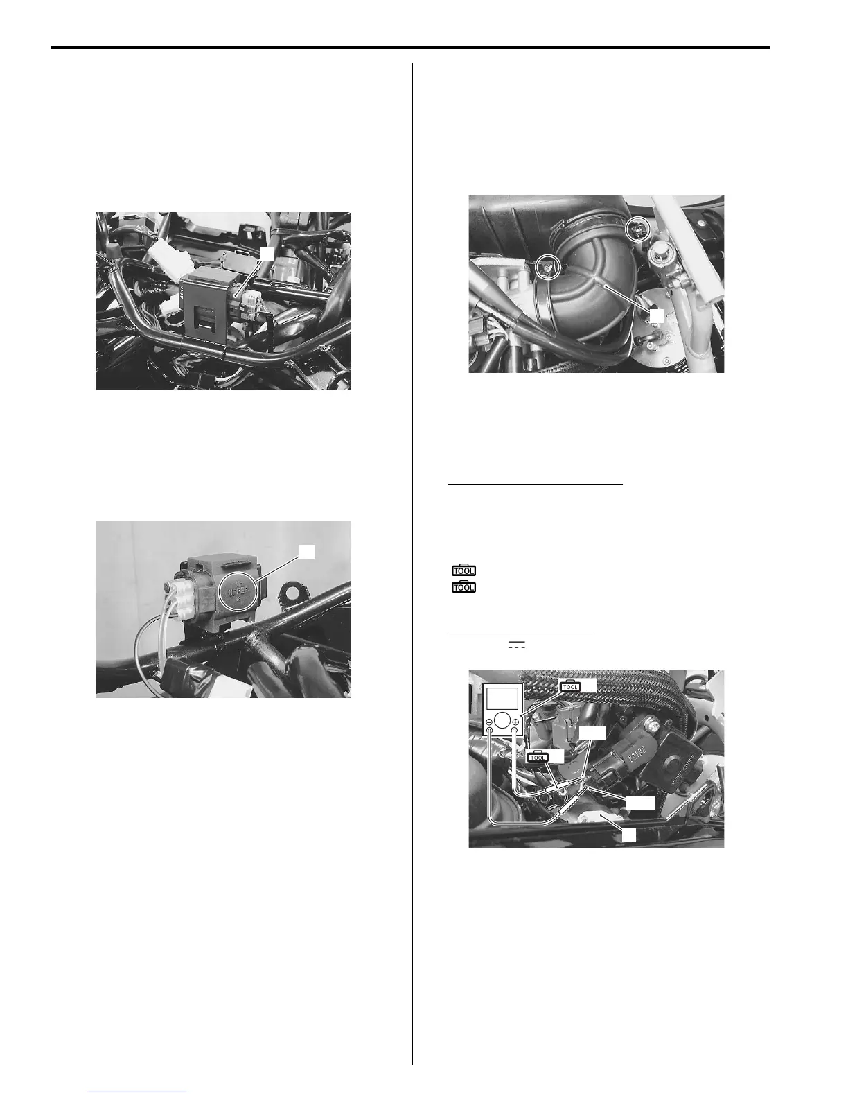
2) Remove the air cleaner box outlet tube (1).
3) Disconnect the STVA lead wire coupler (2).
4) Turn the ignition switch ON.
5) Insert the needle pointed probes to the STP sensor
coupler.
STP sensor output voltage
ST valve is fully closed: 0.5 V
ST valve is fully open: 3.9 V
(Positive terminal: Y/G – Negative terminal: B/Br)
Special tool
(A): 09900–25008 (Multi-circuit tester set)
(B): 09900–25009 (Needle pointed probe
set)
Tester knob indication
Voltage ( )
1
I705H1130009-03
“A”
I705H1130010-02
1
I705H1130011-01
V
2
B/Br
Y/G
(A)
(B)
I705H1130012-01
 Loading...


