Engine Mechanical: 1D-29
Cylinder Head and Related Parts Inspection
B705H11406014
Cylinder Head Distortion
1) Decarbonize the combustion chambers.
2) Check the gasket surface of the cylinder head for
distortion. Use a straightedge and thickness gauge.
Take clearance readings at several places. If
readings exceed the service limit, replace the
cylinder head.
Special tool
: 09900–20803 (Thickness gauge)
Cylinder head distortion
Service limit: 0.05 mm (0.002 in)
Valve Stem Runout
Support the valve using V-blocks, as shown, and check
its runout using the dial gauge. If the runout exceeds the
service limit, replace the valve.
Special tool
(A): 09900–20606 (Dial gauge (1/100 mm))
(B): 09900–20701 (Magnetic stand)
(C): 09900–21304 (V-block (100 mm))
Valve stem runout
Service limit: 0.05 mm (0.002 in)
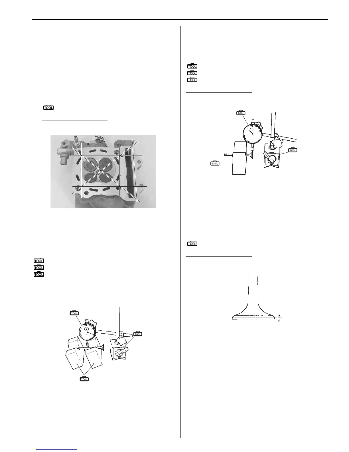
Valve Head Radial Runout
Place the dial gauge at a right angle to the valve head
face and measure the valve head radial runout. If it
measures more than the service limit, replace the valve.
Special tool
(A): 09900–20606 (Dial gauge (1/100 mm))
(B): 09900–20701 (Magnetic stand)
(C): 09900–21304 (V-block (100 mm))
Valve head radial runout
Service limit: 0.03 mm (0.001 in)
Valve Face Wear
Visually inspect each valve face for wear. Replace any
valve with an abnormally worn face. The thickness of the
valve face decreases as the face wears. Measure the
valve face “a”. If it is out of specification replace the
valve with a new one.
Special tool
: 09900–20102 (Vernier calipers)
Valve face thickness “a”
Service limit: 0.5 mm (0.02 in)
I705H1140056-02
(A)
(C)
(B)
I649G1140231-02
(A)
(B)
(C)
I649G1140232-02
“a”
I649G1140233-01
 Loading...


