Brake Control System and Diagnosis: 4A-2
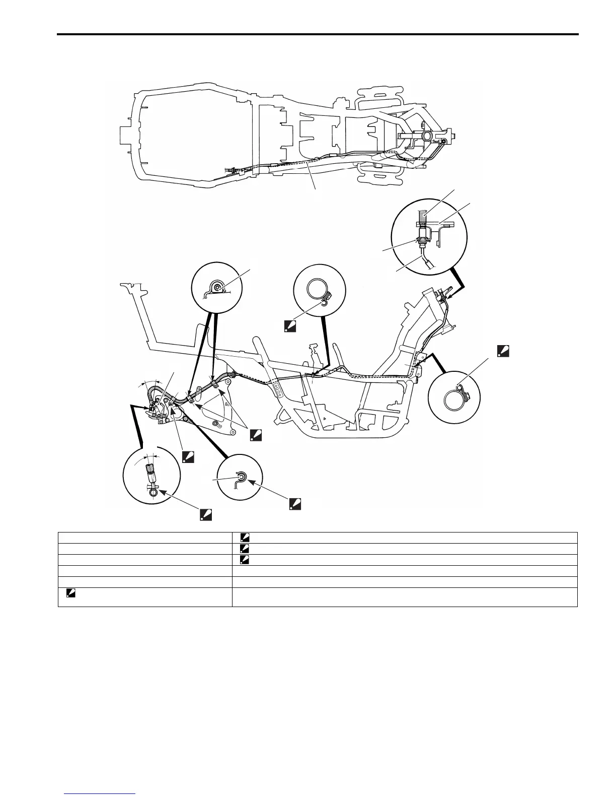
Rear Brake Hose Routing Diagram
B705H14102004
1
1
4
2
3
“B”
“A”
1
“A”
1
2
5
1
“B”
“C”
“a”
“D”
“b”
I705H1410029-03
1. Rear brake pipe “B”: After positioning the clamp with the stopper on the swingarm, tighten the clamp bolt.
2. Rear brake hose “C”: After touching the brake hose union to the stopper, tighten the union bolt to the specified torque.
3. Front cowling plate “D”: Clamp the brake hose firmly.
4. E-ring “a”: 28°
5. Rear brake caliper “b”: 14°
“A”: Clamp the rear brake pipe at white mark
position.
 Loading...


