1D-10 Engine Mechanical:
9) Remove the air cleaner box.
Installation
Install the air cleaner box in the reverse order of
removal. Refer to “Air Cleaner Element Removal and
Installation in Section 0B (Page0B-2)”, “Footboard
Removal and Installation in Section 9D (Page9D-21)”,
“Front Frame Cover Removal and Installation in Section
9D (Page9D-17)” and “Helmet Box Front Cover Removal
and Installation in Section 9D (Page9D-16)”.
Air Cleaner Element Inspection
B705H11406067
Refer to “Air Cleaner Element Inspection in Section 0B
(Page0B-3)”.
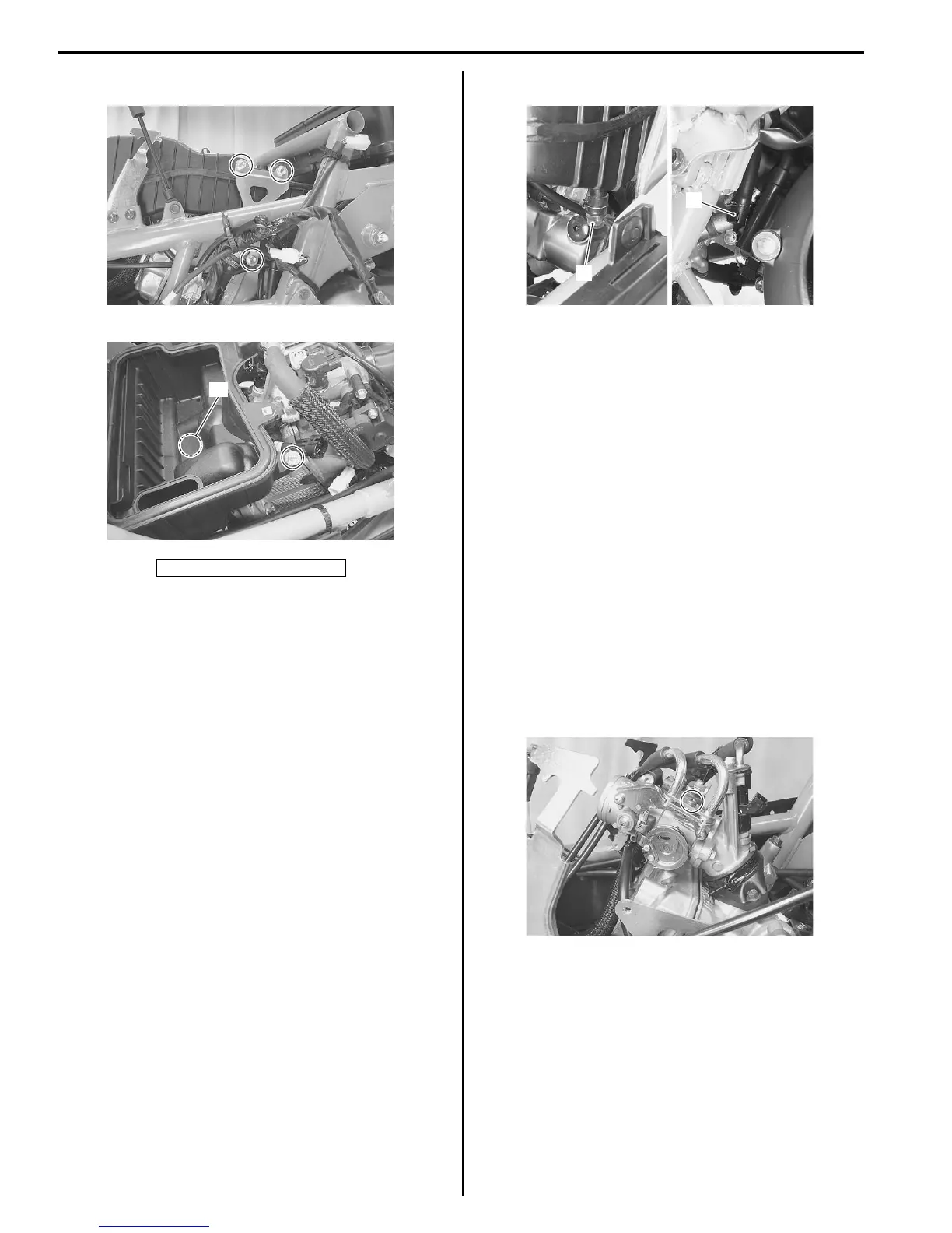
Air Cleaner Drain Plug Inspection
B705H11406068
Inspect the air cleaner drain plugs in the following
procedures:
1) Remove the air cleaner element and inspect the
drain hole on the air cleaner box for clogging.
2) Remove the front frame cover. Refer to “Front Frame
Cover Removal and Installation in Section 9D
(Page9D-17)”.
3) Remove the left side leg shield. Refer to “Side Leg
Shield Removal and Installation in Section 9D
(Page9D-15)”.
4) Visually inspect the drain plugs (1) and (2).
5) Drain water if necessary by removing the plug.
6) Install the removed parts.
Throttle Cable Removal and Installation
B705H11406069
Removal
1) Remove the handlebar covers. Refer to “Handlebar
Cover Removal and Installation in Section 9D
(Page9D-13)”.
2) Remove the front box. Refer to “Front Box Removal
and Installation in Section 9D (Page9D-18)”.
3) Remove the front frame cover. Refer to “Front Frame
Cover Removal and Installation in Section 9D
(Page9D-17)”.
4) Disengage the throttle cable ends from the throttle
case on handlebars. Refer to “Handlebars Removal
and Installation in Section 6B (Page6B-2)”.
5) Remove the throttle cables by disengaging the other
ends from the throttle body.
Installation
Install the throttle cables in the reverse order of removal.
Pay attention to the following point.
• Rout the throttle cables properly. Refer to “Throttle
Cable Routing Diagram (Page1D-2)”.
Throttle Cable Adjustment
B705H11406071
Adjust the throttle cable play. Refer to “Throttle Cable
Play Inspection and Adjustment in Section 0B (Page0B-
11)”.
“A”: Hooked point
I705H1140201-01
“A”
I705H1140202-02
1
2
I705H1140238-01
I705H1140204-01
 Loading...


