Lighting Systems: 9B-8
3) Inspect the dimmer switch for continuity with the
tester. If any abnormality is found, replace the left
handlebar switch assembly with a new one. Refer to
“Handlebars Removal and Installation in Section 6B
(Page6B-2)”.
Special tool
: 09900–25008 (Multi-circuit tester set)
Tester knob indication
Continuity ( )
4) After finishing the dimmer switch inspection, reinstall
the removed parts.
Turn Signal Switch Inspection
B705H19206023
Inspect the turn signal switch in the following
procedures:
1) Remove the meter panel. Refer to “Meter Panel
Removal and Installation in Section 9D (Page9D-
14)”.
2) Disconnect the left handlebar switch coupler (1).
3) Inspect the turn signal switch for continuity with the
tester. If any abnormality is found, replace the left
handlebar switch assembly with a new one. Refer to
“Handlebars Removal and Installation in Section 6B
(Page6B-2)”.
Special tool
: 09900–25008 (Multi-circuit tester set)
Tester knob indication
Continuity ( )
4) After finishing the turn signal switch inspection,
reinstall the removed parts.
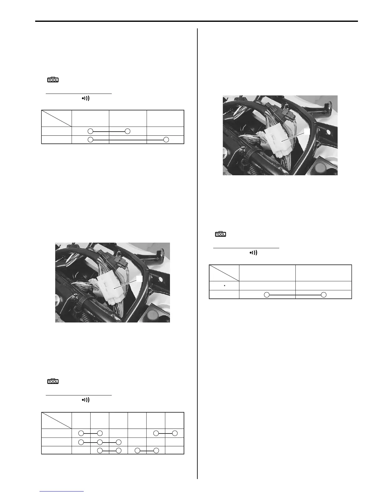
Passing Light Switch Inspection
B705H19206024
Inspect the passing light switch in the following
procedures:
1) Remove the meter panel. Refer to “Meter Panel
Removal and Installation in Section 9D (Page9D-
14)”.
2) Disconnect the left handlebar switch coupler (1).
3) Inspect the passing light switch for continuity with the
tester. If any abnormality is found, replace the left
handlebar switch assembly with a new one. Refer to
“Handlebars Removal and Installation in Section 6B
(Page6B-2)”.
Special tool
: 09900–25008 (Multi-circuit tester set)
Tester knob indication
Continuity ( )
4) After finishing the passing light switch inspection,
reinstall the removed parts.
O/R
Color
Position
HI
LO
YW
I705H1920026-01
1
I705H1920025-01
Color
Position
P
L
R
PUSH
B
Dg
Ch Lg
Sb
I705H1920027-02
1
I705H1920025-01
Color
Position
PUSH
O/R
Y
I705H1920028-01
 Loading...


