1D-12 Engine Mechanical:
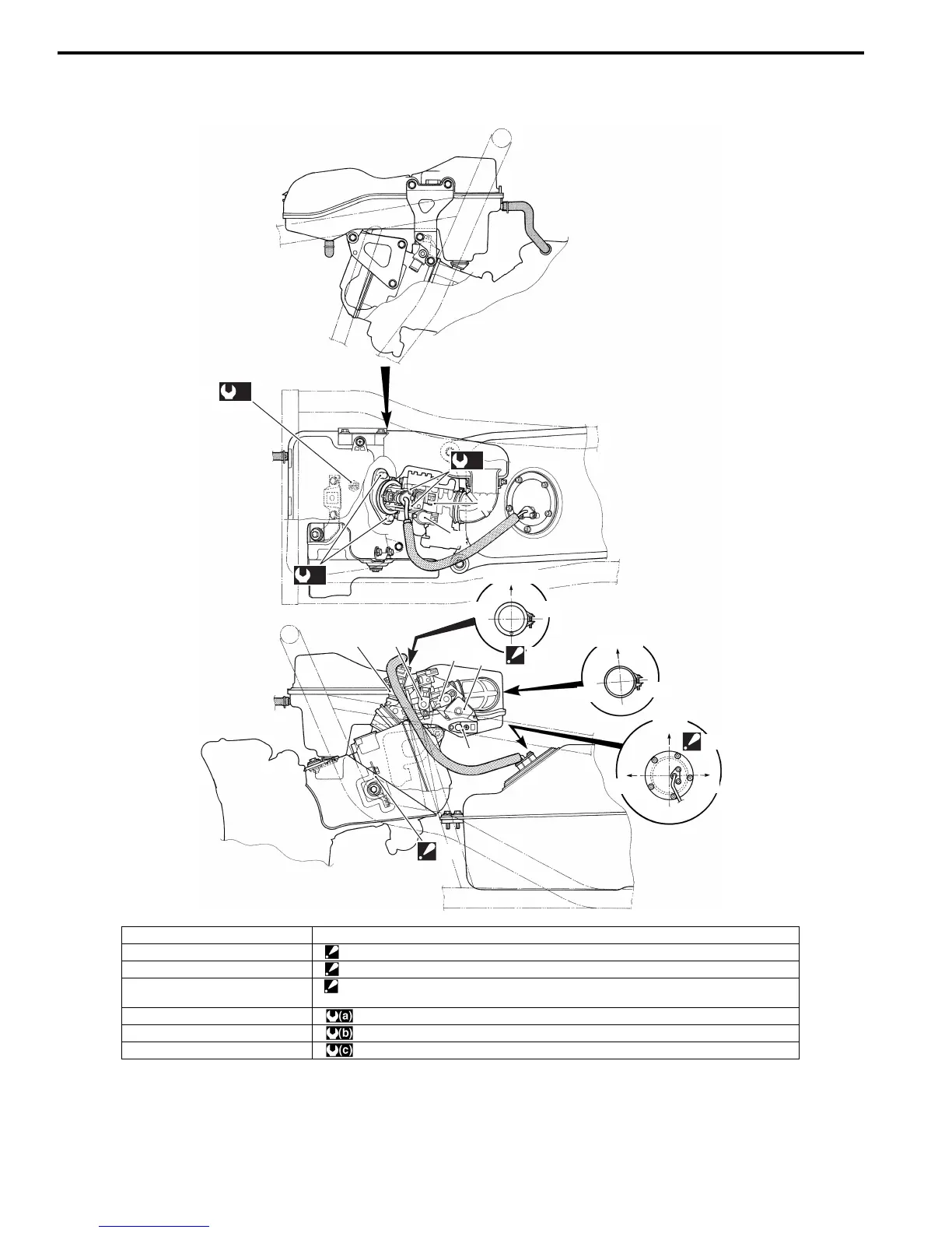
Throttle Body Construction
B705H11406074
2
3
7
8
“A”
“B”
“C”
4
(a)
1
UPSIDE
UPSIDE
RH
RH
RH
LH
LH
LH
FWD
5
6
(b)
(c)
I705H1140237-03
1. ECT sensor 8. IAT sensor
2. IAP sensor “A”: Triangle mark must point downward.
3. ISC valve “B”: Tighten the bracket with the cylinder head bolt (L130).
4. Fuel injector “C”: Tighten each bolt in temporary and final stages in numerical order on bolt.
Refer to “Fuel Pump Disassembly and Assembly in Section 1G (Page1G-10)”.
5. TP sensor : 12 N⋅m (1.2 kgf-m, 8.5 lb-ft)
6. STP sensor : 10 N⋅m (1.0 kgf-m, 7.0 lb-ft)
7. STVA : 10 N⋅m (1.0 kgf-m, 7.0 lb-ft)
 Loading...


