Engine General Information and Diagnosis: 1A-4
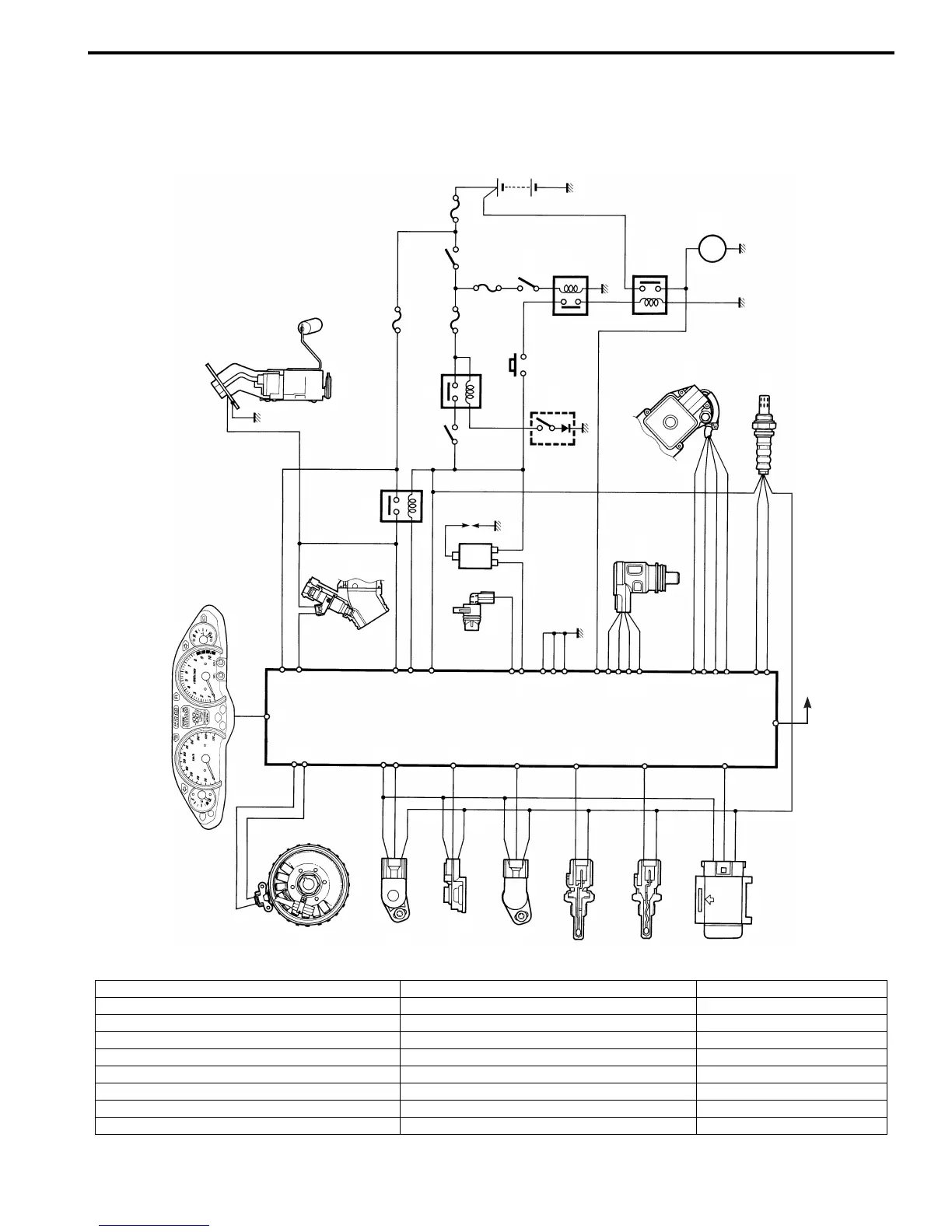
Schematic and Routing Diagram
FI System Wiring Diagram
B705H11102001
30 A
10 A
15 A
10 A
3
9
14
7
21
5
16
17
13
12
36
15
34
35
8
44
43
37
30
33
22
1
19
11
20
23
6
24
25
29
2
ECM
“A”
“B”
“C”
“D”
“E”
“F”
“G”
“H”
“I”
“J”
“V”
“W”
“X”
“Y”
“K”
“L”
“M”
“N”
“Z”
“O”
“P”
“Q”
“R”
“S”
“T”
“U”
I705H1110032-05
“A”: Crankshaft position sensor (CKPS) “J”: Fuel pump (FP) “S”: Starter button
“B”: Throttle position sensor (TPS) “K”: Fuel pump relay (FP relay) “T”: Brake light switch
“C”: Intake air pressure sensor (IAPS) “L”: Ignition coil “U”: Brake relay
“D”: Secondary throttle position sensor (STPS) “M”: Speed sensor “V”: Side-stand switch
“E”: Engine coolant temperature sensor (ECTS) “N”: Idle speed control valve (ISC valve) “W”: Starter relay
“F”: Intake air temperature sensor (IATS) “O”: Secondary throttle valve actuator (STVA) “X”: Starter motor
“G”: Tip-over sensor (TOS) “P”: Engine stop switch “Y”: Battery
“H”: HO2 sensor “Q”: Side-stand relay “Z”: SDS
“I”: Fuel injector “R”: Ignition switch

 Loading...


