Charging System: 1J-6
3) Measure the voltage between the terminals using the
multi circuit tester as indicated in the following table.
If the voltage is not within the specified value,
replace the regulator/rectifier with a new one.
Special tool
: 09900–25008 (Multi-circuit tester set)
Tester knob indication
Diode test ( )
Unit: V
NOTE
If the tester reads 1.4 V and below when the
tester probes are not connected, replace its
battery.
4) Install the regulator/rectifier.
5) Install the front leg shield. Refer to “Front Leg Shield
Removal and Installation in Section 9D (Page9D-
14)”.
Generator Removal and Installation
B705H11A06003
Removal
1) Drain engine oil.
2) Remove the side leg shield. Refer to “Side Leg
Shield Removal and Installation in Section 9D
(Page9D-15)”.
3) Remove the generator cover. Refer to “CKP Sensor
Removal and Installation in Section 1C (Page1C-1)”.
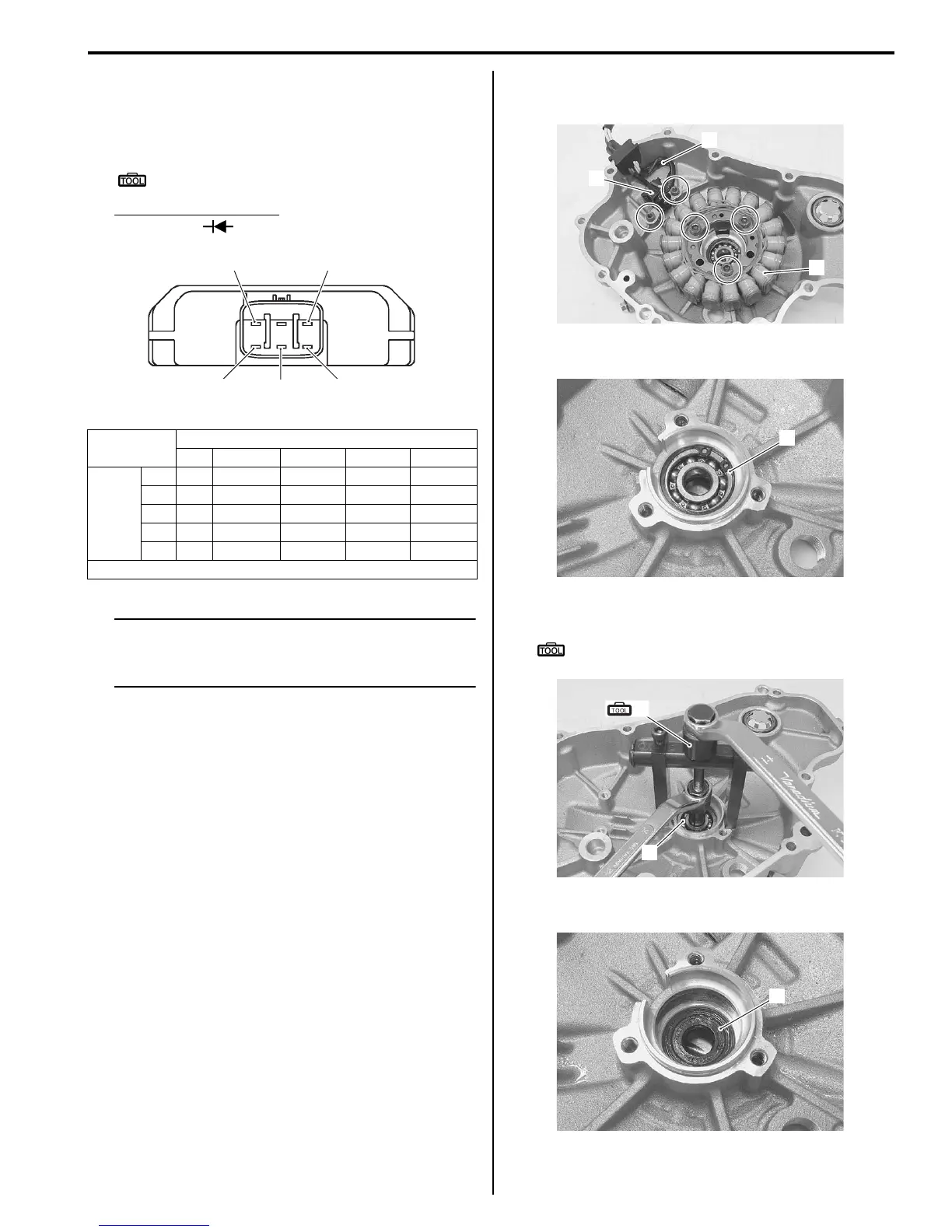
4) Remove the generator stator (1), CKP sensor (2)
and lead wire guide (3).
5) Remove the snap ring (4).
6) Remove the bearing (5) using the special tool.
Special tool
(A): 09921–20240 (Bearing remover set)
7) Remove the oil seal (6).
(+) tester probe
AB C D E
(–)
tester
probe
A — 0.4 – 0.7 0.4 – 0.7 0.4 – 0.7 0.5 – 1.2
B * — * * 0.4 – 0.7
C * * — * 0.4 – 0.7
D * * * — 0.4 – 0.7
E* * * * —
*1.4 V and more (tester’s battery voltage)
A
B
C
D
E
I705H11A0009-02
1
3
2
I705H11A0010-03
4
I705H11A0011-03
5
(A)
I705H11A0013-03
6
I705H11A0014-03
 Loading...


