Steering / Handlebar: 6B-4
Left side
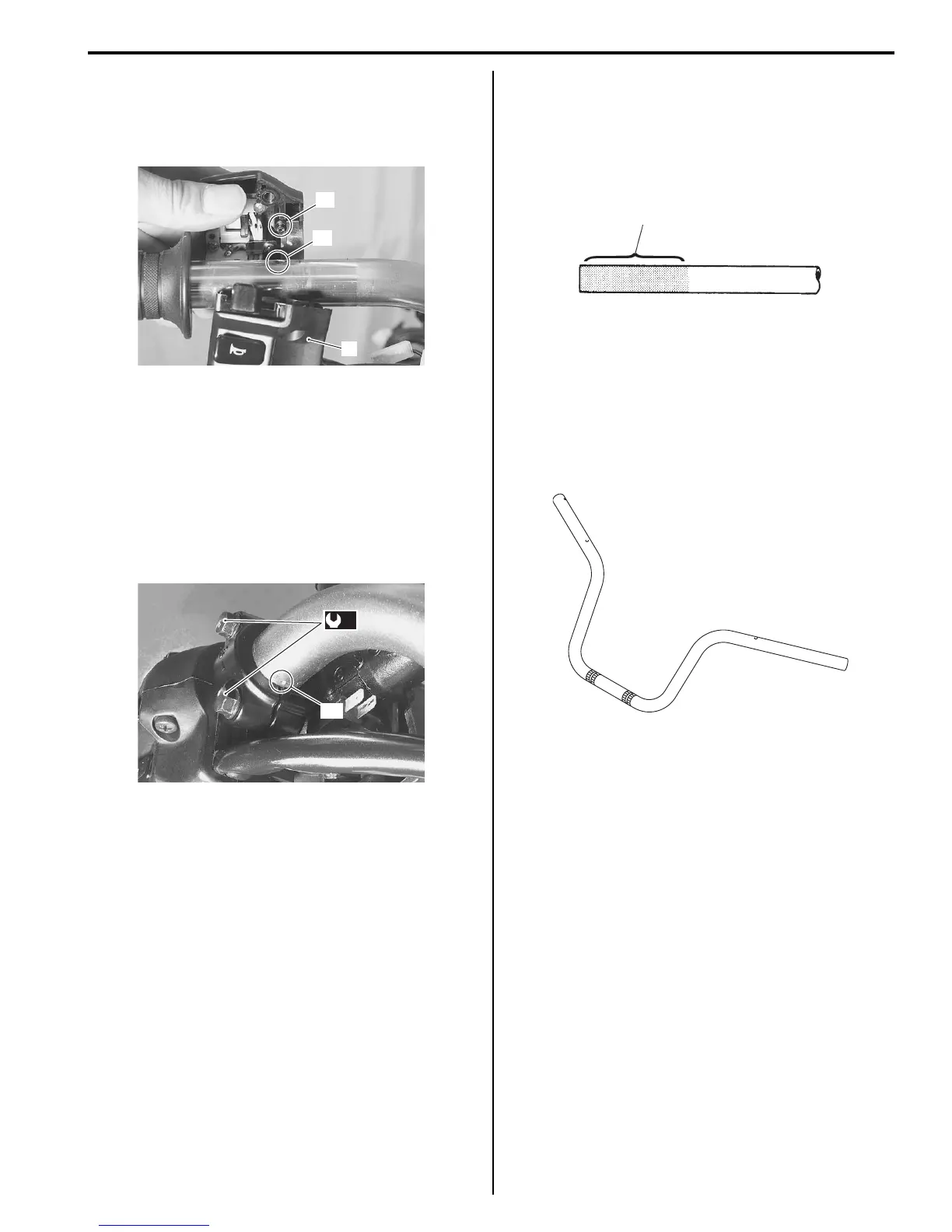
• Install the left handlebar switch box (1) to the
handlebars by engaging the stopper “A” with the hole
“B” on the handlebars.
• Install the brake master cylinder onto the handlebars,
align the master cylinder holder’s mating surface with
punch mark “C” on the handlebars.
• Tighten the upper bolt first temporarily to provide
clearance on the lower side and then tighten both the
bolts to the specified torque.
Tightening torque
Master cylinder bolt (a): 10 N·m (1.0 kgf-m, 7.0 lb-
ft)
• Connect the rear brake light switch lead wire couplers.
• Apply a handle grip bond “D” onto the left handlebar
before installing the handlebar grip.
: Handle grip bond (Handle grip bond
(commercial available))
Handlebars Inspection
B705H16206009
Refer to “Handlebars Removal and Installation (Page6B-
2)”.
Inspect the handlebars for distortion and damage.
If any defect are found, replace the handlebars with a
new one.
1
“A”
“B”
I705H1620008-03
(a)
“C”
I705H1620009-02
“D”
I705H1620031-01
I705H1620034-01
 Loading...


