Fuel System: 1G-13
Fuel Pump Relay Inspection
B705H11706006
Refer to “Electrical Components Location in Section 0A
(Page0A-7)”.
Inspect the fuel pump relay in the following procedures:
1) Remove the front leg shield. Refer to “Front Leg
Shield Removal and Installation in Section 9D
(Page9D-14)”.
2) Remove the fuel pump relay (1).
3) First, check for insulation with the tester between
terminals (2) and (3). Next, check for continuity
between (2) and (3) with 12 V voltage applied,
positive (+) to terminal (4) and negative (–) to
terminal (5). If continuity does not exist, replace the
relay with a new one.
Fuel Mesh Filter Inspection
B705H11706020
Inspect the fuel mesh filter in the following procedures:
1) Remove the fuel mesh filter. Refer to “Fuel Pump
Disassembly and Assembly (Page1G-10)”.
2) If the fuel mesh filter is clogged with foreign particles,
it hinders smooth gasoline flow resulting in loss of
engine power. Such a filter should be cleaned by
blowing with compressed air.
NOTE
When the fuel mesh filter is dirtied
excessively, replace the fuel filter cartridge
with a new one.
3) After finishing the fuel mesh filter inspection, reinstall
the fuel mesh filter. Refer to “Fuel Mesh Filter
Inspection (Page1G-13)”.
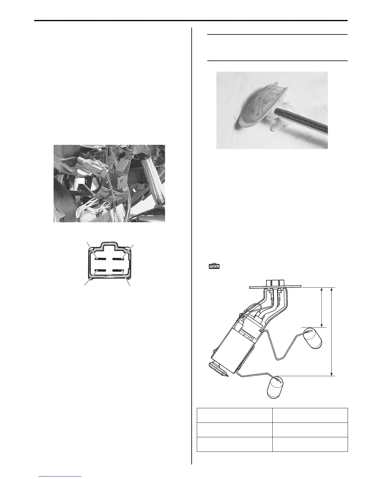
Fuel Level Gauge Inspection
B705H11706021
Inspect the fuel level gauge in the following procedures:
1) Remove the fuel pump assembly. Refer to “Fuel
Pump Disassembly and Assembly (Page1G-10)”.
2) Check for resistance between the terminals for each
of the following float position.
If the resistance measured is out of specification,
replace the fuel gauge with a new one.
Special tool
: 09900–25008 (Multi-circuit tester set)
1
I705H1170023-03
2
5
3
4
I705H1170024-02
Float position
Resistance between
terminals
F: 86.4 mm
from tank mating face
Approx. 9 – 11 Ω
E: 186.3 mm
from tank mating face
Approx. 129 – 131 Ω
I705H1170025-01
86.4 mm
186.3 mm
F
E
I705H1170033-06
 Loading...


