4A-9 Brake Control System and Diagnosis:
• After setting the brake hose union to the stopper,
tighten the union bolt to the specified torque.
CAUTION
!
The seal washers should be replaced with the
new ones to prevent fluid leakage.
Tightening torque
Brake hose union bolt (b): 23 N·m (2.3 kgf-m, 16.5
lb-ft)
• Bleed air from the brake system. Refer to “Air
Bleeding from Brake Fluid Circuit (Page4A-4)”.
Front Master Cylinder / Brake Lever
Disassembly and Assembly
B705H14106024
Refer to “Front Brake Master Cylinder Assembly
Removal and Installation (Page4A-8)”.
Disassembly
1) Remove the dust cover (1), brake lever (2) and
brake light switch (3).
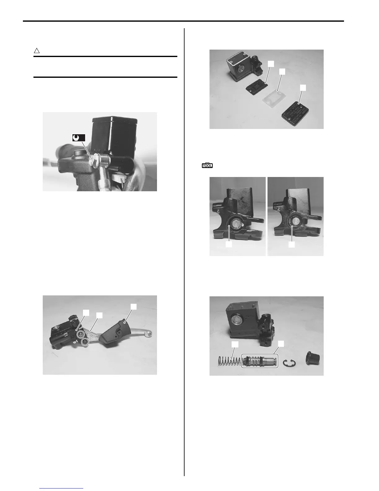
2) Remove the reservoir cap (4), plate (5) and
diaphragm (6).
3) Pull out the dust boot (7) and remove the snap ring
(8) using the special tool.
Special tool
: 09900–06108 (Snap ring pliers)
4) Remove the following parts from the master cylinder.
• Piston/Cup set (9)
• Spring (10)
(b)
I705H1410008-01
1
2
3
I705H1410009-01
5
6
4
I705H1410010-02
7
8
I705H1410011-01
10
9
I705H1410012-01
 Loading...


