Brake Control System and Diagnosis: 4A-6
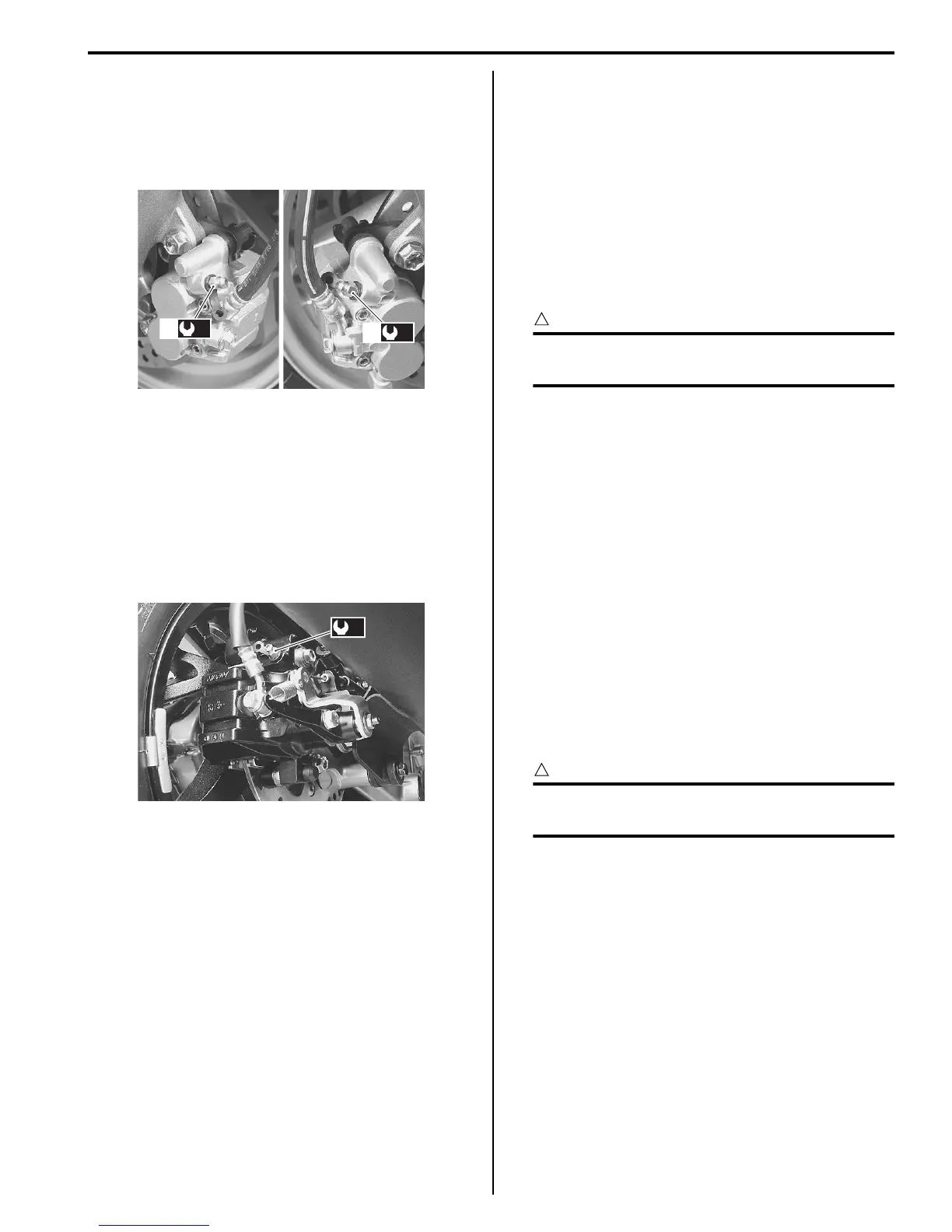
7) Close the air bleeder valve (1) and disconnect the
clear hose.
Tightening torque
Air bleeder valve (Front brake) (a): 6.0 N·m (0.6
kgf-m, 4.5 lb-ft)
8) Fill the reservoir with new brake fluid to the upper
line of the reservoir.
Rear brake
Brake fluid replacement in the same manner as the front
brake.
Tightening torque
Air bleeder valve (Rear brake) (a): 6.0 N·m (0.6 kgf-
m, 4.5 lb-ft)
Front Brake Hose Removal and Installation
B705H14106021
Removal
1) Remove the front leg shield. Refer to “Front Leg
Shield Removal and Installation in Section 9D
(Page9D-14)”.
2) Drain brake fluid. Refer to “Brake Fluid Replacement
(Page4A-5)”.
3) Remove the front brake hoses. Refer to “Front Brake
Hose Routing Diagram (Page4A-1)”.
Installation
CAUTION
!
The seal washers should be replaced with the
new ones to prevent fluid leakage.
1) Install the front brake hose. Refer to “Front Brake
Hose Routing Diagram (Page4A-1)”.
2) Bleed air from the front brake system. Refer to “Air
Bleeding from Brake Fluid Circuit (Page4A-4)”.
3) Reinstalled remove the parts.
Rear Brake Hose Removal and Installation
B705H14106022
Removal
1) Remove the right foot board. Refer to “Footboard
Removal and Installation in Section 9D (Page9D-
21)”.
2) Drain brake fluid. Refer to “Brake Fluid Replacement
(Page4A-5)”.
3) Remove the rear brake hose. Refer to “Rear Brake
Hose Routing Diagram (Page4A-2)”.
Installation
CAUTION
!
The seal washers should be replaced with the
new ones to prevent fluid leakage.
1) Install the rear brake hose. Refer to “Rear Brake
Hose Routing Diagram (Page4A-2)”.
2) Bleed air from the rear brake system. Refer to “Air
Bleeding from Brake Fluid Circuit (Page4A-4)”.
3) Reinstalled remove the parts.
(a)
1
(a)
1
I705H1410004-02
(a)
I705H1410025-01
 Loading...


