1D-32 Engine Mechanical:
Valve Guide Replacement
B705H11406051
1) Remove the cylinder head. Refer to “Engine Top
Side Disassembly (Page1D-16)”.
2) Remove the valves. Refer to “Cylinder Head
Disassembly and Reassembly (Page1D-25)”.
3) Using the valve guide remover, drive the valve guide
out toward the intake or exhaust camshaft side.
Special tool
(A): 09916–43210 (Valve guide remover/
installer)
NOTE
• Discard the removed valve guide sub
assemblies.
• Only oversized valve guides are available
as replacement parts. (Part No. 11115-
32C71)
4) Refinish the valve guide holes in the cylinder head
using the reamer and handle.
CAUTION
!
When refinishing or removing the reamer
from the valve guide hole, always turn it
clockwise.
Special tool
(B): 09916–34561 (Valve guide reamer (11.3
mm))
(C): 09916–34542 (Reamer handle)
5) Cool down the new valve guides in a freezer for
about one hour and heat the cylinder head to 100 –
150 °C (212 – 302 °F) with a hot plate.
CAUTION
!
Do not use a burner to heat the valve guide
hole to prevent cylinder head distortion.
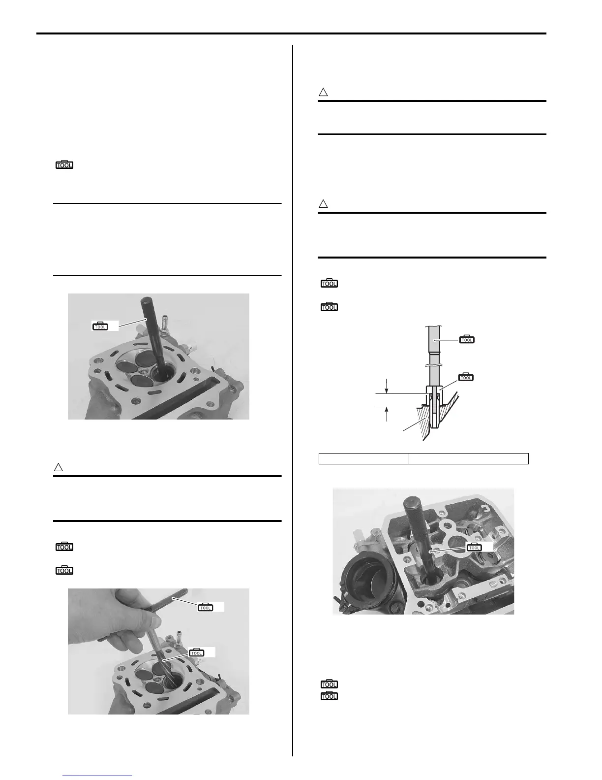
6) Apply engine oil to each valve guide (1) and valve
guide hole.
7) Drive the guide into the guide hole using the valve
guide installer.
CAUTION
!
Failure to oil the valve guide hole before
driving the new guide into place may result in
a damaged guide or head.
Special tool
(A): 09916–43210 (Valve guide remover/
installer)
(D): 09916–53330 (Attachment)
8) After installing the valve guides, refinish their guiding
bores using the reamer. Be sure to clean and oil the
guides after reaming.
Special tool
(C): 09916–34542 (Reamer handle)
(E): 09916–33210 (Valve guide reamer (4.5
mm))
(A)
I705H1140060-02
(B)
(C)
I705H1140061-03
“A”: Cylinder head “a”: 13.3 mm (0.52 in)
“A”
“a”
(A)
(D)
I705H1140023-04
(A)
I705H1140062-02
 Loading...


