6B-3 Steering / Handlebar:
Installation
Install the handlebars in the reverse order of removal.
Pay attention to the following points:
• Set the handlebars so that its punch mark “A” aligns
with the mating surface of the left handlebar holder.
• Apply thread lock to the handlebar clamp bolts.
• Tighten the forward handlebar clamp bolts first
temporarily to provide clearance on the rear side and
then tighten both the bolts to the specified torque.
: Thread lock cement 99000–32030 (Thread
Lock Cement Super 1303 or equivalent)
Tightening torque
Handlebar clamp bolt (a): 23 N·m (2.3 kgf-m, 16.5
lb-ft)
NOTE
First tighten the handlebar clamp bolts (front
ones) to the specified torque.
• After installing the steering, the following adjustments
are required before driving.
– Cable routing (Refer to “Throttle Cable Routing
Diagram in Section 1D (Page1D-2)”.)
– Throttle cable play (Refer to “Throttle Cable Play
Inspection and Adjustment in Section 0B (Page0B-
11)”.)
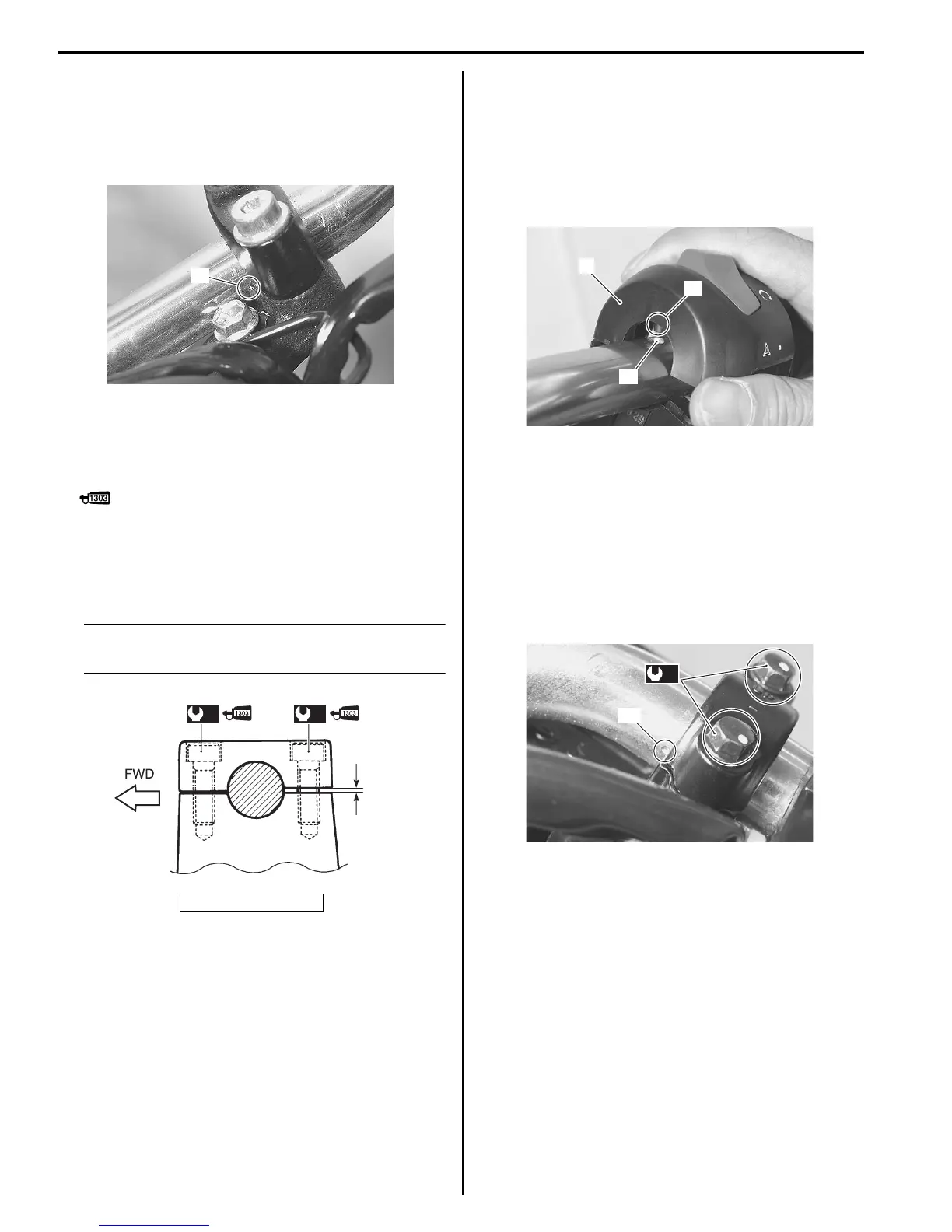
Right side
• Install the right handlebar switch box (1) to the
handlebars by engaging the stopper “A” with the hole
“B” on the handlebars.
• Adjust the throttle cable play. Refer to “Throttle Cable
Play Inspection and Adjustment in Section 0B
(Page0B-11)”.
• Install the brake master cylinder onto the handlebars,
align the master cylinder holder’s mating surface with
punch mark “C” on the handlebars.
• Tighten the upper bolt first temporarily to provide
clearance on the lower side and then tighten both the
bolts to the specified torque.
Tightening torque
Master cylinder bolt (a): 10 N·m (1.0 kgf-m, 7.0 lb-
ft)
• Connect the front brake light switch lead wire
couplers.
“a”: Clearance
“A”
I705H1620004-02
(a)(a)
“a”
I705H1620005-04
1
“A”
“B”
I705H1620006-02
(a)
“C”
I705H1620007-02

 Loading...


