CLUTCH
L3301, L3901, L4701, WSM
2-S13
(2) Separating Clutch Assembly
Clutch Assembly
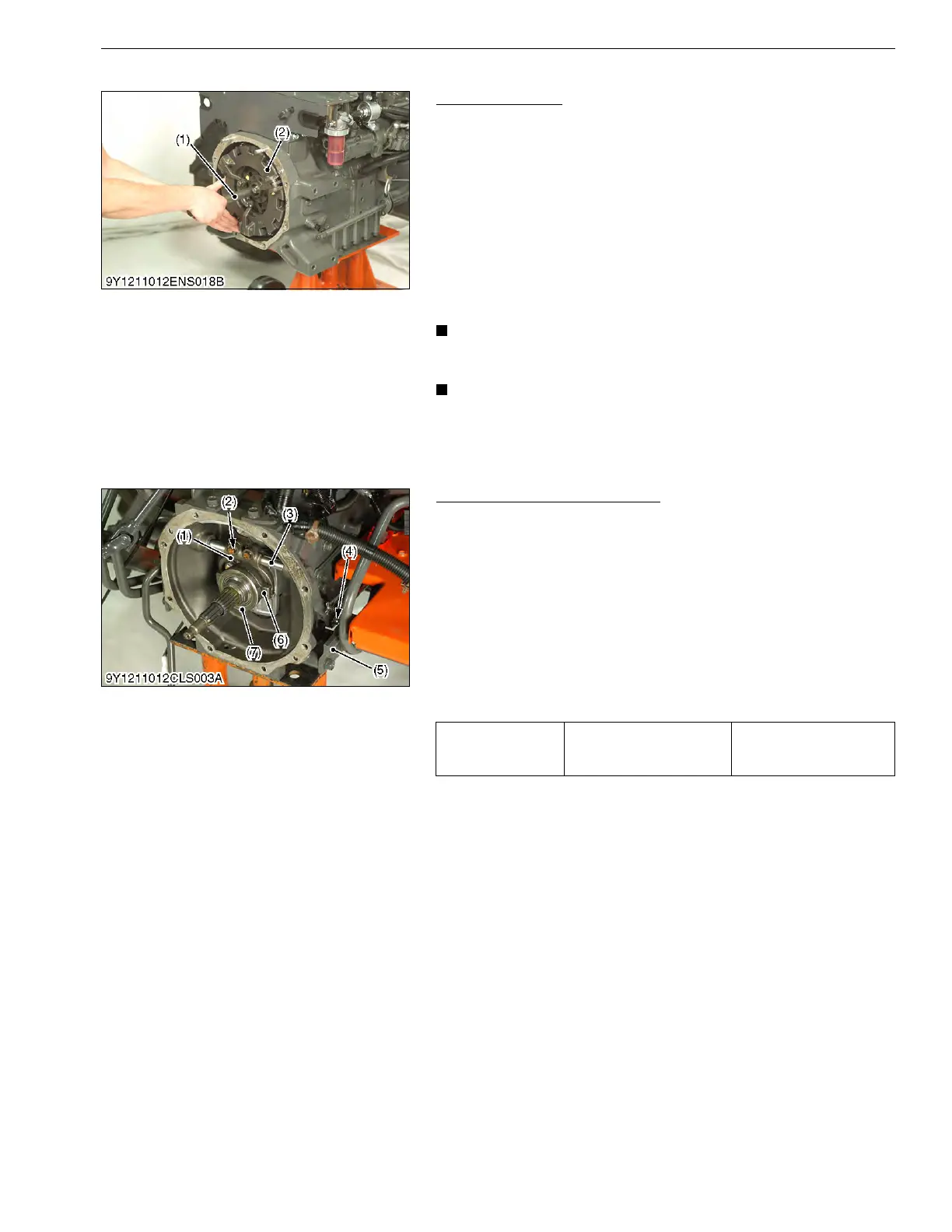
1. Insert the clutch center tool (1).
2. Remove the clutch assembly (2) together with the clutch center
tool.
(When reassembling)
• Direct the shorter end of the clutch disc boss toward the
flywheel.
• Apply molybdenum disulphide (Three Bond 1901 or equivalent)
to the splines of clutch disc boss.
• Insert the pressure plate, noting the position of straight pins.
• After docking the engine and the clutch housing case, assemble
the outer parts, referring to the picture.
• Be sure to align the center of disc and flywheel by inserting
the clutch tool set.
• Be sure to align the center of disc and flywheel by inserting
the clutch tool set.
9Y1211012ENS0027US0
Release Hub and Clutch Lever
1. Remove the step brackets (5).
2. Disconnect the clutch rod (4) from the clutch lever (3).
3. Remove the release fork mounting screws (2).
4. Draw out the clutch lever (3) and remove the release fork (1).
5. Remove the thrust bearing (7) and clutch holder (6) as a unit.
(When reassembling)
• Inject grease to the clutch holder (6).
• Make sure the direction of the clutch release fork (1) is correct.
• Apply grease to contact face of the clutch release fork and
clutch holder.
• Apply grease to the clutch lever (3).
9Y1211012CLS0006US0
(1) Clutch Center Tool (2) Clutch Assembly
Tightening torque
Release fork mounting
screw
23.5 to 27.5 N·m
2.4 to 2.8 kgf·m
17.4 to 20.3 lbf·ft
(1) Clutch Release Fork
(2) Screw
(3) Clutch Lever
(4) Clutch Rod
(5) Step Bracket
(6) Clutch Holder
(7) Thrust Bearing
 Loading...