HYDRAULIC SYSTEM
L3301, L3901, L4701, WSM
8-S25
(Continued)
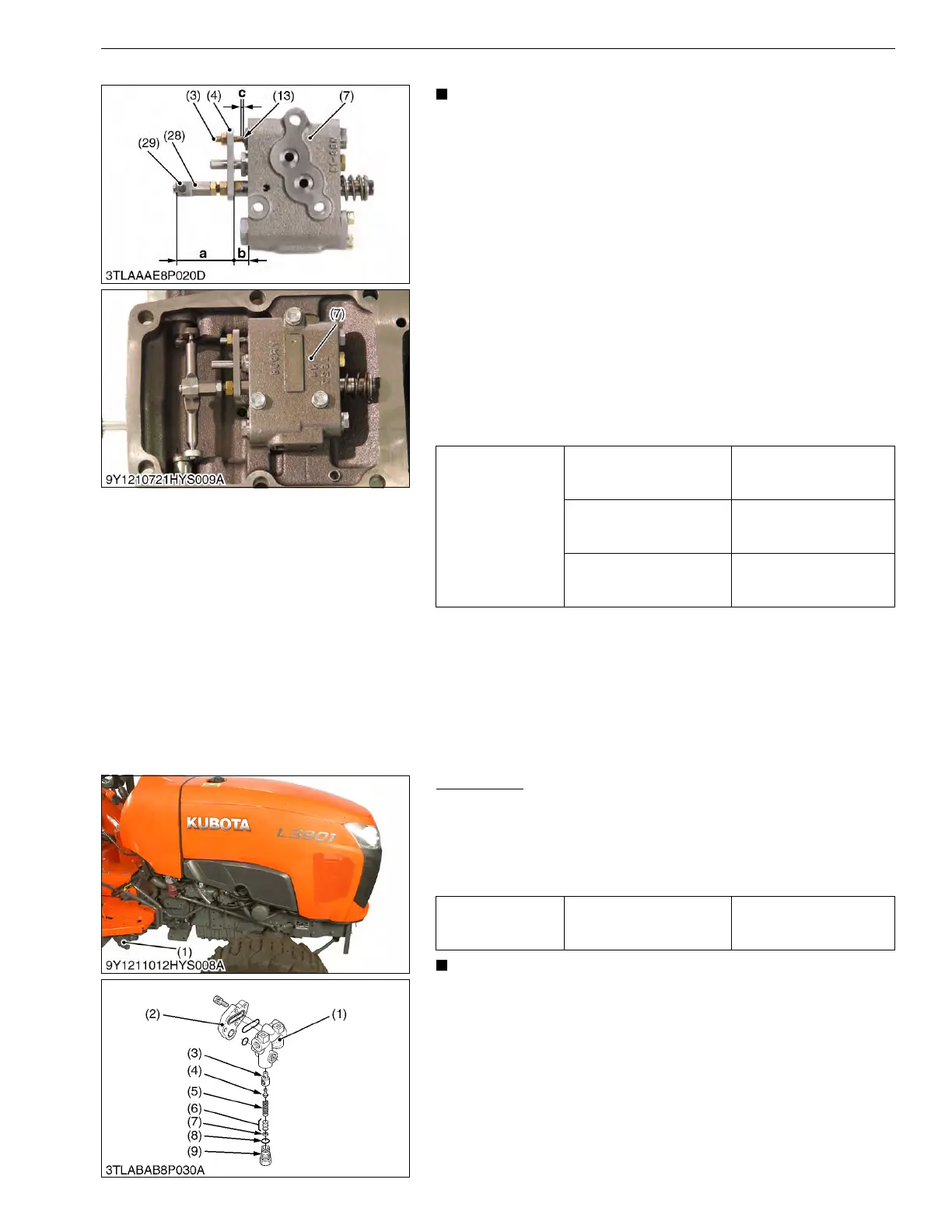
• Set screw (3) and spool joint 1 (28) are adjusted to very
close accuracy. Do not disassemble them unless
necessary.
If disassembled due to unavoidable reasons, be sure to
make the following adjustments before assembling.
Spool joint 1 (2)
1. Turn and adjust the spool joint 1 (28) so that the dimension "a"
between the spool joint 2 (29) and the plate 1 (4) is 48.0 mm
(1.89 in.).
2. After adjustment, be sure to adjust the position control feedback
rod.
Set screw (3)
1. Turn and adjust the set screw (3) so that the clearance "c"
between the set screw (3) and the poppet 2 (13) becomes 0.1
to 0.2 mm (0.0039 to 0.0079 in.).
(When reassembling)
• Assemble the control valve to the hydraulic cylinder as shown in
the picture.
9Y1211012HYS0016US0
[4] RELIEF VALVE
Relief Valve
1. Remove the plug (9), and draw out the spring (5) and the poppet
(4).
2. Remove the valve seat (3).
(When reassembling)
• Be careful not to damage the O-rings.
• After disassembling and assembling the relief valve, be
sure to adjust the relief valve setting pressure.
9Y1211012HYS0017US0
Tightening torque
Plug 1
39.2 to 58.8 N·m
4.0 to 6.0 kgf·m
28.9 to 43.4 lbf·ft
Plug 2
29.4 to 49.0 N·m
3.0 to 5.0 kgf·m
21.7 to 36.2 lbf·ft
Unload plug
39.2 to 58.8 N·m
4.0 to 6.0 kgf·m
28.9 to 43.4 lbf·ft
(3) Set Screw
(4) Plate 1
(7) Valve Body
(13) Poppet 2
(28) Spool Joint 1
(29) Spool Joint 2
a: Dimension
b: Dimension
c: Clearance
Tightening torque Relief valve plug
35 to 44 N·m
3.5 to 4.5 kgf·m
26 to 32 lbf·ft
(1) Front Hydraulic Block
(2) Cap
(3) Valve Seat
(4) Poppet
(5) Spring
(6) Adjusting Shim
(7) Washer
(8) O-ring
(9) Plug
 Loading...