174 Rockwell Automation Publication 193-UM015E-EN-P - October 2015
Chapter 5 Operating Modes
• Option Match Trip or must be enabled in TripEnableC (Parameter
186)
• O
perator Station must be enabled in Mismatch Action (Parameter
233)
• An operator station must be selected in Operator Station Type
(Paramete
r 224)
Or
• O
ption Match Warning must be enabled in WarningEnableC
(Paramete
r 192)
• Operator Station must be disabled in Mismatch Action (Parameter
233)
• An operator station must be selected in Operator Station Type
(Paramete
r 224)
6. Communication Fault & Idle Override (Parameter 346) must be enabled.
7. Network Fault Override (Parameter 347) must be enabled.
8. Feedback Timeout Trip in TripEnableC (Parameter 186) or Feedback
Time
out Warning in WarningEnableC (Parameter 192) must be enabled.
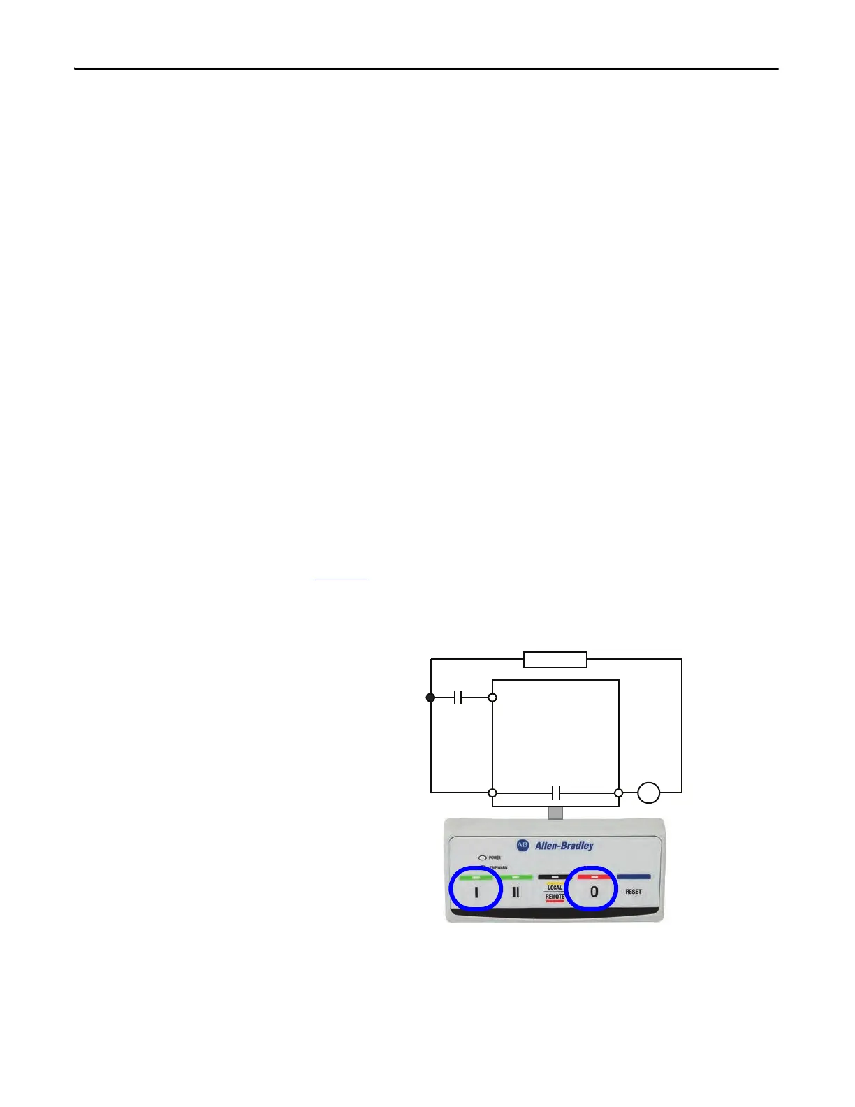
Wiring Diagram
The E300 relay’s Output Relay 0 is wired as a control relay in which the relay is
controlled by the communication network and opens when a trip event occurs.
Figure 79
is a wiring diagram of a non-reversing starter with the contactor
auxiliary wired to Input 0 and Output Relay 0 configured as a control relay.
Figure 79 - Non-reversing Starter (Operator Station) with Feedback Wiring Diagram
R03 R04
Relay 0
Run
E300
Control Power
I- Run 0- Stop
Run Aux
IN 0

 Loading...


