182 Rockwell Automation Publication 193-UM015E-EN-P - October 2015
Chapter 5 Operating Modes
Wiring Diagram
The E300 relay’s Output Relay 0 is wired as a control relay in which the relay is
energized when Input 0 is active and Input 1 is momentarily active. Output Relay
0 de-energizes when Input 0 is momentarily de-active or when a trip event occurs.
Figure 88
is a wiring diagram of a non-reversing starter with three wire control
and an Output Relay 0 configured as a control relay.
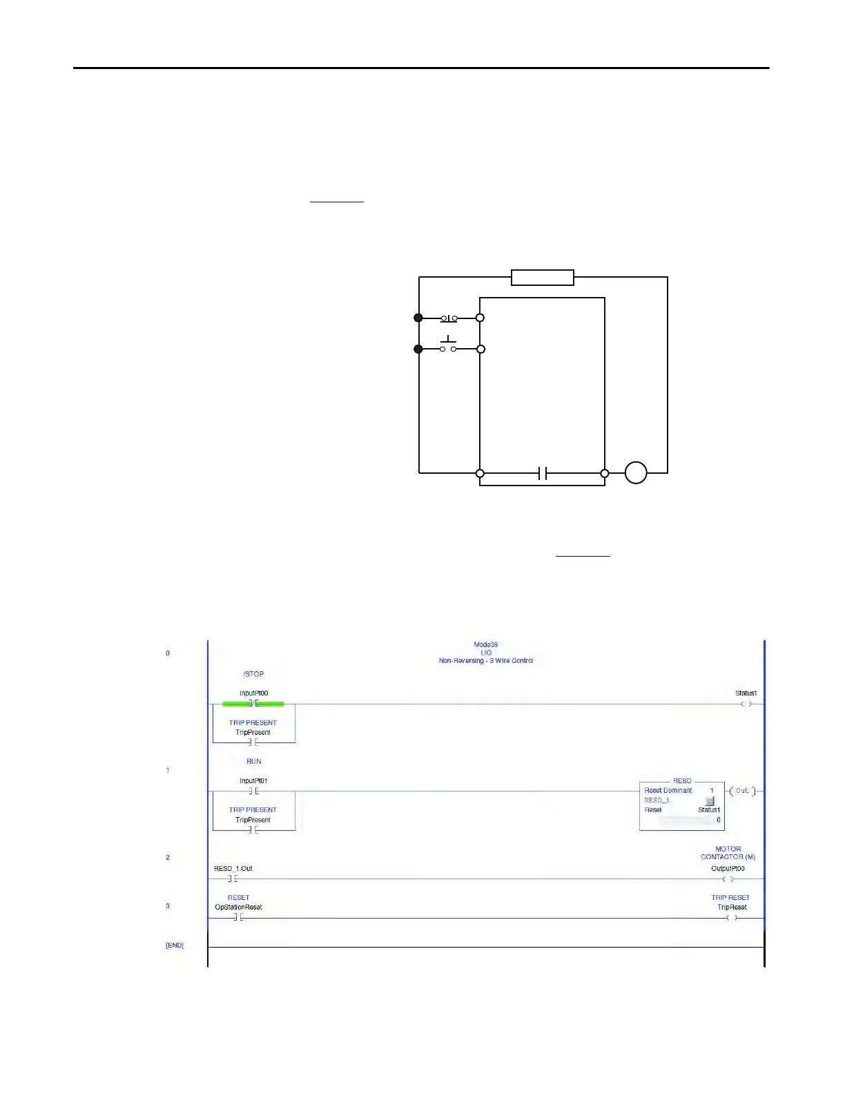
Figure 88 - Non-reversing Starter (Local I/O) – Three-wire Control Wiring Diagram
DeviceLogix Program
The DeviceLogix program that is shown in Figure 89 is automatically loaded and
enabled in the E300 on power-up or when Operating Mode (Parameter 195) is
set to a value of 38.
Figure 89 - Non-reversing Starter (Local I/O) – Three-wire Control DeviceLogix Program
R03 R04
Relay 0
Run
E300
IN 0
IN 1
Stop
Run
Control Power

 Loading...


