184 Rockwell Automation Publication 193-UM015E-EN-P - October 2015
Chapter 5 Operating Modes
6. Communication Fault & Idle Override (Parameter 346) must be enabled.
7. Network Fault Override (Parameter 347) must be enabled.
Wiring Diagram
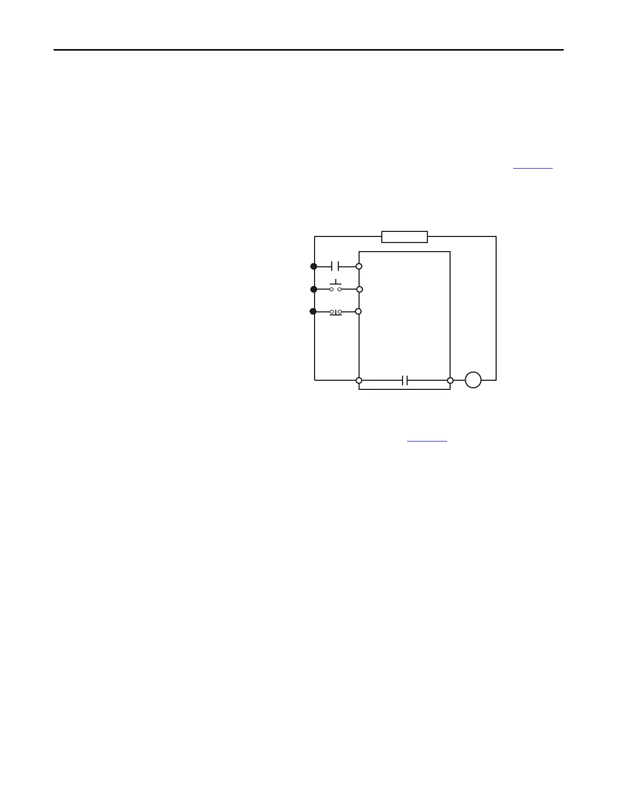
The E300 relay’s Output Relay 0 is wired as a control relay in which the relay is
controlled by the state if Input 1 and opens when a trip event occurs. Figure 91
is
a wiring diagram of a non-reversing starter with three wire control and Output
Relay 0 configured as a control relay.
Figure 91 - Non-reversing Starter (Local I/O) – Three-wire Control with Feedback Wiring Diagram
DeviceLogix Program
The DeviceLogix program that is shown in Figure 92 is automatically loaded and
enabled in the E300 on powerup or when Operating Mode (Parameter 195) is set
to a value of 39.
R03 R04
Relay 0
Run
E300
IN 0
IN 1
Stop
Run
Control Power
Run Aux
IN 2

 Loading...


