•
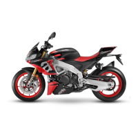
Resistance of the wires read on the display = 0.47 Ohm
•
Effective resistance stage 1 = 0.67-0.47 = 0.20 Ohm
•
If there is a significant difference between one stage and another (other than 0.20 Ohm),
this means that the alternator is defective and must be replaced.
RESISTANCE MEASUREMENT
Winding stage Ambient temperature (ohm) Afterwards heat stabilisation (ohm)
Stage 1 0.15 - 0.30 0.20 - 0.35
Stage 2 0.15 - 0.30 0.20 - 0.35
Stage 3 0.15 - 0.30 0.20 - 0.35
Empty voltage
•
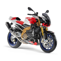
Disconnect the six-way connector (1).
•
Make a special cable harness using
two connectors that can be coupled
with those on the alternator side and
the chassis side of the motorcycle. The
outgoing wires from pins 1 and 5 must
maintain the continuity of the positive
and negative of the pick-up, otherwise
the engine will not start; while the out-
going cables from pins 2, 4, 6 (alterna-
tor side) must have the ends free in
order to perform the appropriate ac-
tion.
CAUTION
KEEP THE THREE ENDS OF THE FREE CABLES WELL
SEPARATED TO AVOID DANGEROUS SHORT CIRCUITS.
•
For a correct detection of the alternator voltage, the measurements must be carried out using
alternatively the 3 ends of the free cables: stage "1" (outgoing cables from pins 2 and 4),
Electrical system RS 125 - Tuono 125 - Euro 4
ELE SYS - 114
 Loading...