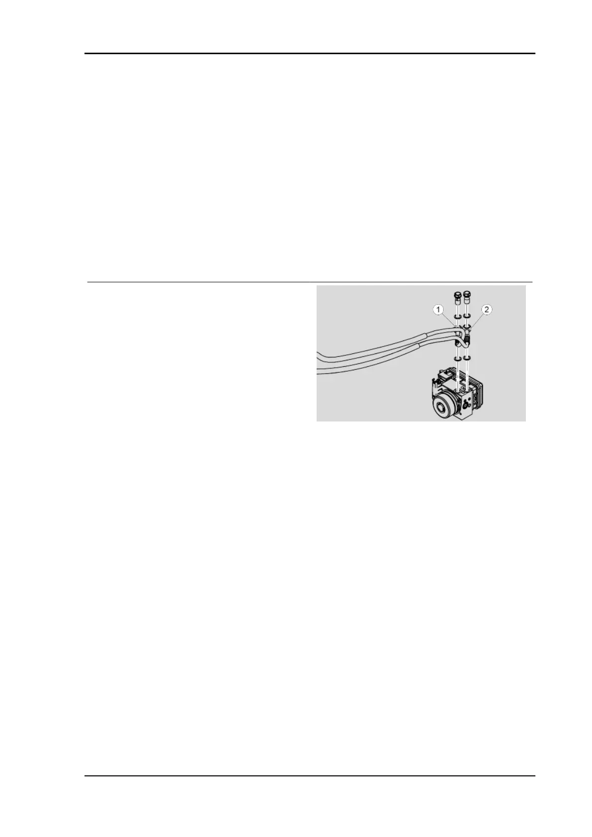
ABS functional diagram key
1. Front system circuit.
2. Front brake master cylinder.
3. Front brake control lever.
4. ABS control unit.
5. Front brake calliper.
6. Front brake circuit inlet solenoid valve (normally open).
7. Front brake circuit low pressure accumulator.
8. Front brake outlet circuit solenoid valve (normally closed).
9. DC electric motor.
10.Hydraulic circuit pump (ABS).
Inlets and outlets:
1. Inlet from front brake master cylinder.
2. Outlet to front brake calliper.
ABS OPERATION
General specifications:
•
The ABS inlet valve (6) is normally open and only closes when the system intervenes to
prevent wheel lock-up.
•
The outlet valve (8) is normally closed and only opens when the system intervenes to prevent
wheel lock-up.
•
With the system in stand-by mode, the ABS processor controls the wheel speed instant by
instant to assess any slippage of the wheels.
•
When in standby state, the system does not intervene at all when the rider brakes; the
functions of the braking system are identical to the system without ABS.
Stages in ABS cycle:
A - Brake activation: the rider starts braking as he would usually do.
B - Pressure reduction: coincides with the recognition of the dangerous situation (wheel slippage
exceeds the threshold): The system closes the inlet valve (6) and temporarily opens the outlet valve
(8).
In this condition, the rider cannot increase the pressure exerted on the calliper (5) and the system
partially reduces the pressure in the calliper itself. The excess fluid temporarily fills the reservoir inside
the ABS modulator until the ABS modulator (10) automatically triggers and returns fluid towards the
brake master cylinder (2 ).
RS 125 - Tuono 125 - Euro 4 Braking system
BRAK SYS - 279
 Loading...