Open circuit: circuit interruption.
Troubleshooting
Short-circuit to positive:
•
Disconnect the fan control relay (No. 42 in electrical circuit diagram), turn the ignition switch
to ON and measure the voltage at PIN 1 of the relay connector leading to the wiring harness
side: if the voltage is 12V, repair the wiring harness, if the voltage is zero, replace the relay.
Short circuit to negative:
•
Disconnect the fan control relay (No. 42 in electrical circuit diagram) and the control unit.
•
Check that the cable between the fan control relay (PIN 1) and the ECU (PIN 24) is insulated
from ground. Repair the wiring harness if necessary.
Open circuit:
•
Check the ECU and relay connectors.
•
Check continuity of the cable between the relay connector (PIN 1) and the ECU connector
(PIN 2).
•
Check continuity of the cable between the relay connector (PIN 2) and the secondary fuse
box.
•
Check continuity between PIN 1 and PIN 2 of the relay. If continuity is not confirmed, replace
the relay.
RUN/STOP switch
Function
Indicates the control unit if the rider wishes to en-
able engine start-up or to keep the engine running
Operation / Operating principle
If the driver wants to shut off the engine or to dis-
able engine start-up, the switch should be open,
i.e. the Marelli control unit should not detect volt-
age at PIN 4 of the control unit connector
Level in electrical circuit diagram
Start-up enabling switches
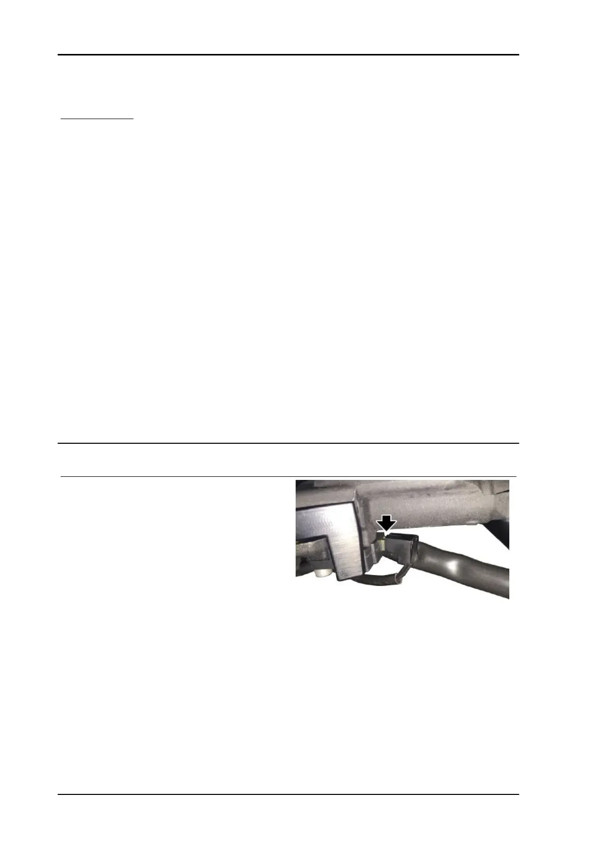
Position
•
Sensor: right light switch
•
Connector: next to the headstock, right
side
Electrical specifications
•
STOP position: open circuit
Electrical system RS 125 - Tuono 125 - Euro 4
ELE SYS - 142
 Loading...