CHECKING THE STARTER MOTOR
•
To carry out the check, power up the
motor with a 12 V 9 AH battery.
•
Win an AC ammeter clamp measure
the steady running absorbed current
(after 5 seconds).
Correct value 50 - 60 A.
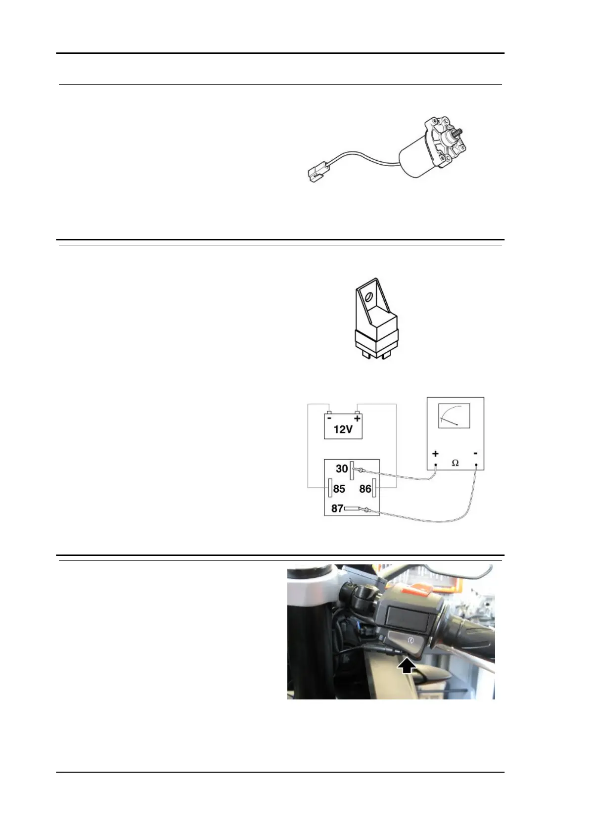
CHECKING THE STARTER MOTOR RELAY
•
To check that the relay is operating
correctly:
•
Power the two male terminals (85 - 86)
with a 12 V voltage.
•
Using a tester (in ohmmeter mode)
check the continuity between the other
two terminals (87 - 30).
Correct value with relay energised: 0 Ohm
Correct value with relay not energised: infinite
ohm
•
If the values do not correspond to those
indicated, replace the relay.
STARTER COMMAND
Function
Commands engine starting through the injection
control unit.
Operation / Operating principle
The starter button, brake switches, No. 25 starter
relay and the injection control unit are involved, via
PINs 5 and 10.
Level in electrical circuit diagram
Start enable signals, Starting
Position
Electrical system RS 125 - Tuono 125 - Euro 4
ELE SYS - 118
 Loading...