6. Replacing Parts
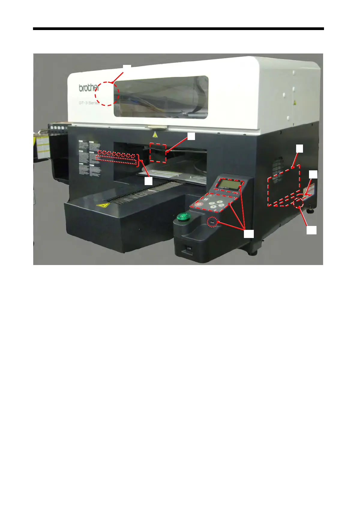
6-2-2. Control Box, Operation Panel, PCBs
6
1
2
3
4
5
7
1. Main PCB
Located in
side of the Control Box to control printer operation.
2. Power PCB
Located inside of the Control Box to supply power to the whole printer.
3. Surge Absorber PCB
Decreases the power line noise.
4. Panel PCB / LCD Unit / USB Host PCB
Located in the Operation Panel to control the display and input operation.
5. Maintenance PCB
Located at the rear of the Maintenance Unit to control the maintenance operation.
6. Carriage PCB
Located on the top of the Carriage Assy on which the Print Heads are mounted, to control ink firing for
maximum 8 print heads by each.
7. Ink Sensor PCB, Ink Switch PCB
Located at the back of the Ink Cartridge to detect the Cartridge and the amount of ink remained.
GT-3 Series
310
 Loading...