SPI operation SPI communications
Digi XBee® 3 Cellular LTE Cat 1 AT&T Smart Modem User Guide
151
SPI communications
The XBee Smart Modem supports SPI communications in slave mode. Slave mode receives the clock
signal and data from the master and returns data to the master. The following table shows the
signals that the SPI port uses on the device.
Signal Function
SPI_MOSI
(MasterOut,SlaveIn)
Inputs serial data from the master
SPI_MISO(Master
In,Slave Out)
Outputs serial data to the master
SPI_SCLK
(SerialClock)
Clocks data transfers on MOSI and MISO
SPI_SSEL
(SlaveSelect)
Enables serial communication with the slave
SPI_ATTN (Attention) Alerts the master that slave has data queued to send. The XBee Smart
Modem asserts this pin as soon as data is available to send to the SPI
master and it remains asserted until the SPI master has clocked out all
available data.
In this mode:
n SPI clock rates up to 4.8 MHz are possible.
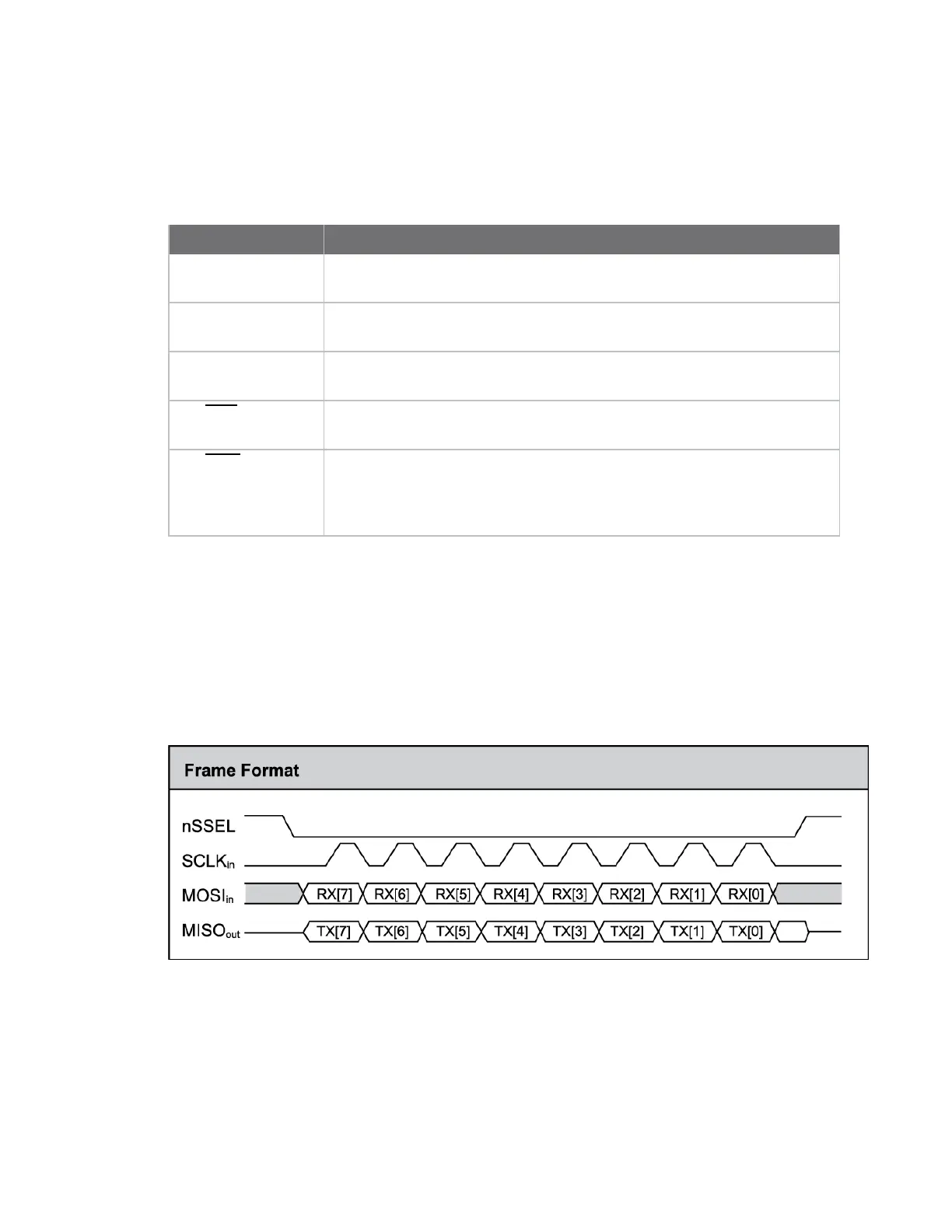
n Data is most significant bit (MSB) first; bit 7 is the first bit of a byte sent over the interface.
n Frame Format mode 0 is used. This means CPOL= 0 (idle clock is low) and CPHA = 0 (data is
sampled on the clock’s leading edge).
n The SPI port only supports API Mode (AP = 1).
The following diagram shows the frame format mode 0 for SPI communications.
SPI mode is chip to chip communication. We do not supply a SPI communication option on the device
development evaluation boards.