AT commands I/O settings commands
Digi XBee® 3 Cellular LTE Cat 1 AT&T Smart Modem User Guide
209
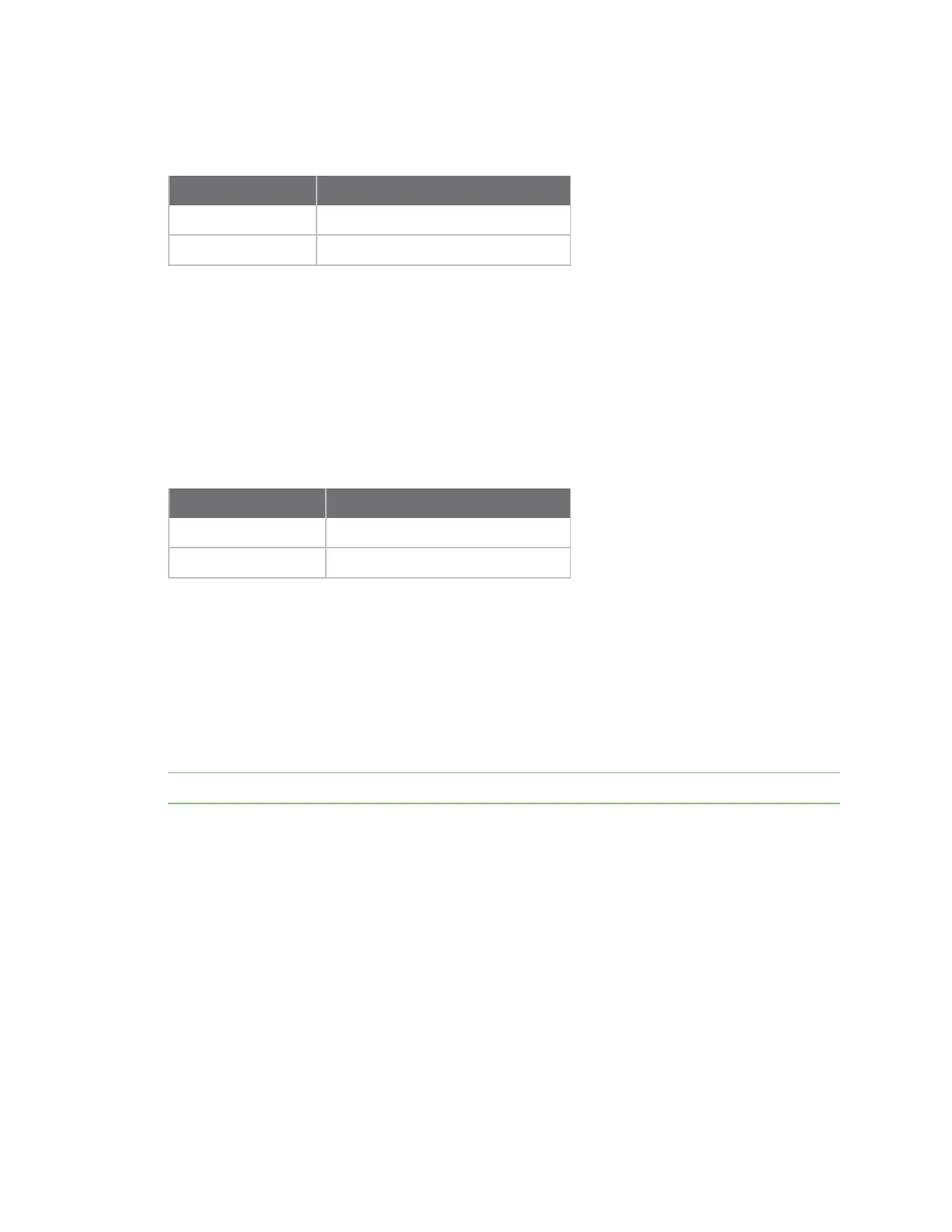
Parameter range
0, 1
Parameter Description
0 Disabled
1 UART DOUT enabled
Default
1
P4 (DIO14/DIN)
Sets or displays the DIO14/DIN configuration (pin 3).
Parameter range
0 - 1
Parameter Description
0 Disabled
1
UART DIN enabled
Default
1
PD (Pull Direction)
The resistor pull direction bit field (1 = pull-up, 0 = pull-down) for corresponding I/O lines that are set
by PR (Pull-up/down Resistor Enable).
If the bit is not set in PR, the device uses PD.
Note Resistors are not applied to disabled lines.
See PR (Pull-up/down Resistor Enable) for bit mappings, which are the same.
Parameter range
0x0 – 0x7FFF
Default
0 – 0x7FFF
PR (Pull-up/down Resistor Enable)
Sets or displays the bit field that configures the internal resistor status for the digital input lines.
Internal pull-up/down resistors are not available for digital output pins, analog input pins, or for
disabled pins.
Use the PD command to specify whether the resistor is pull-up or pull-down.
 Loading...


