Data Transfer from CAD Files | CAD import (option 42)
8
HEIDENHAIN | TNC 620 | Conversational Programming User's Manual | 10/2017
327
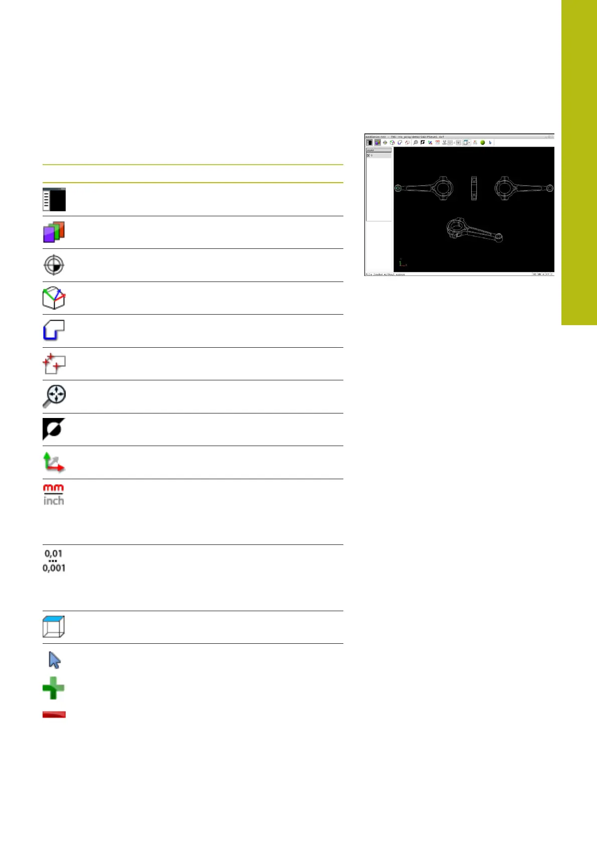
Basic settings
The basic settings specified below are selected using the icons in
the toolbar.
Icon Setting
Show or hide the Window List view to expand
the Graphics window
Display of the various layers
Set a preset
Set the datum
Select the contour
Select hole positions
Set the zoom to the largest possible view of the
complete graphics
Change the background color (black or white)
Switch between 2-D and 3-D mode. The active
mode is color-highlighted
Set the unit of measure, mm or inch, for the
file. The control then outputs the contour
program and the machining positions in this
unit of measure. The active unit of measure is
highlighted in red
Set resolution: The resolution specifies how
many decimal places the control will use
when generating the contour program. Default
setting: 4 decimal places with mm and 5
decimal places with inch
Switch between various view of the model e.g.
Top
Selection and deselection:
The active + symbol is the same as the pressed
Shift key, and the active – symbol is the same
as the pressed CTRL key. The active cursor
symbol is the same as the mouse
The following icons are displayed by the control only in certain
modes.
 Loading...