8.
CYLINDER/PISTON
SERVICE
INFORMATION
TROUBLESHOOTING
CVLlNDER REMOVAL
PISTON
REMOVAL
SERVICE INFORMATION
GENERAL
8-'
8-
2
8
-3
8-3
CYLINDER/ PISTON INSPEC
TION
PISTON INSTALLATION
C
VlINDER
INSTALLATION
8-'
8-7
8-7
T
he
engin
e
must
be
removed
from
Ihe
frame
10
perform
the
opera
ti
ons
in this section.
Ca
msh
aft
l
ub
ri
catio
n oil is fed
to
th"
cyli
nder
head
through
an
orifice
in
the
cylin
der
head. cyl
inder
and
cran
~
case.
Be
sure
Ihal
this
ori
fice is
not
cl
ogged
and Ihat
tho
Q·rings
and
dow(!1 p ins are in place before i
nst
alli
ng
the
cylinder.
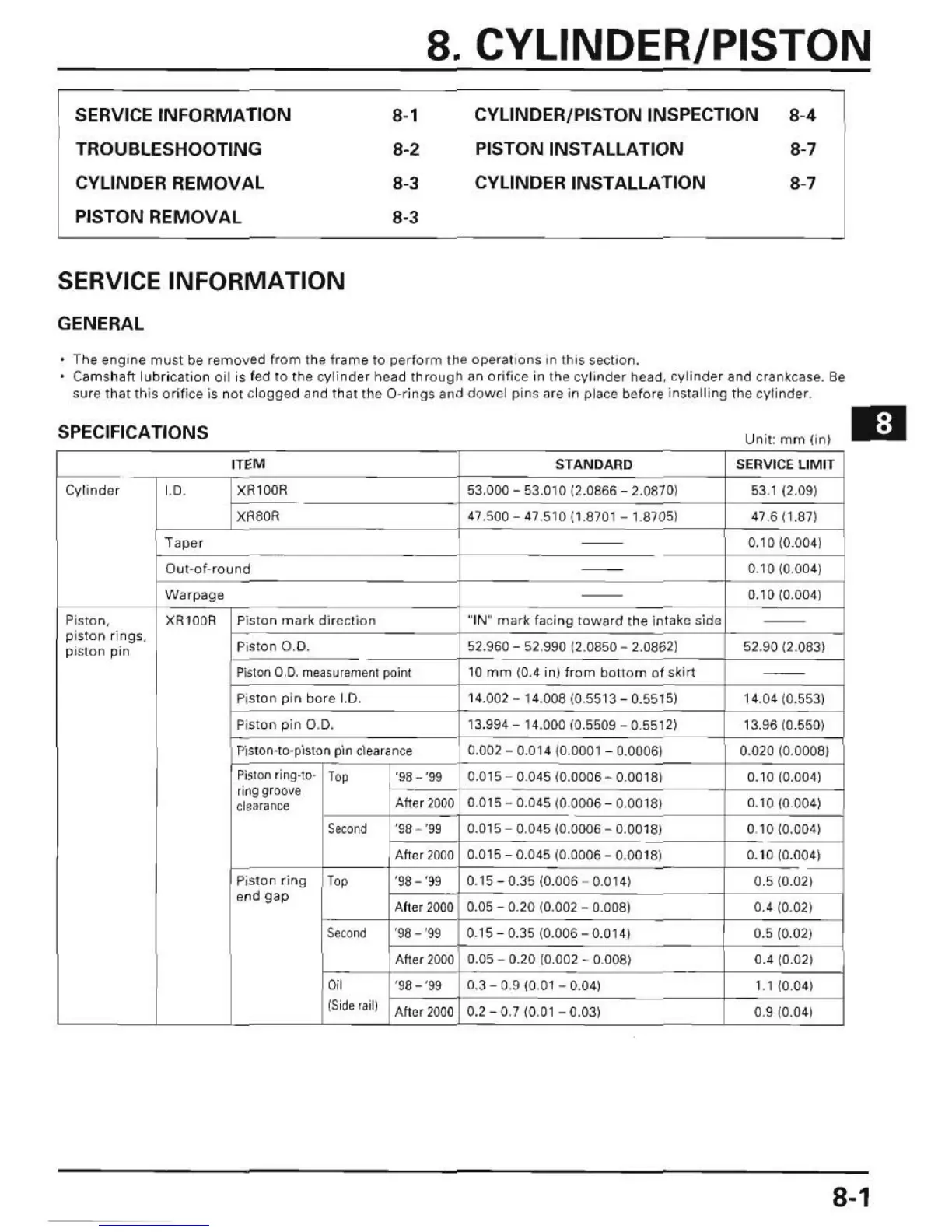
SPECIFICATIONS
Unit
"
mm
(in)
lTliM
STAN
DARD SERVI
CE
LI
MIT
Cyli
nder
1.
0 .
XAtOOR
5)
.000 - 53.010 (2.0866 - 2.08701
53112
.
091
XR80R
47.500 - 47.510 (1 8701 _ 1.8705)
4
7,6(1.87)
"Ta
p
er
--
0.10W
.
0041
Out-
of
-round
--
0.
10(0004)
W~rp~g
e
--
0.10 (0.004)
Piston.
XR
IO
OR
PiSlOn mark direction
-'N"
mar
k lacing
toward
th
e intake
sida
--
pist
on
ri
ngs,
Piston 0 .0 . 52.960
- 52.990 (2.0850 - 2.0862) 52.
90
(2
.083)
piston pin
Pi.t
on
0 .0.
me~su
r
emMt
point
10
mm (0.4 in) from
bottom
of skirt
--
Pi
ston
pi
n bore
1.
0 . 14.002 - 14.00810.
5513-
0.551
5)
t 4.0410.553)
Pi
sto
n pin 0 .
0.
13.994 - 14.000 (0.5509 - 0.5512) t3.96 (0.550)
Vls
ton·to·piston p 'IO
clea
r
~nce
0.002 - 0,014 (0.0001 - 0.0006) 0.020 (0.0008)
Piston
ring·to·
T,p
'98 - '99 0.Q15
0,045 (0.0006
- 0.0018) 0.10 (0.004)
r
ing
groove
Afte
r
2000
durance
0,015 - 0.045 (0.0006 - 0,0018) 0.10
(0
.
00
4)
Second
'98 - '99 0.015
0.045(0.0006
- 0.001
8)
0.10 (0.004)
A
ft
er
2000
0.015
0,045(0
.0006 - 0.001
8)
0,10
(0
.004)
Pist
on
ri
rl
g
Top
'98-
'99
0.15 - 0.35 (0.006 - 0,014)
_
C-
0.5 (0.02)
end
gap
A
ft
er
2000
0.05 - 0.
20
(0
.002 -
O,OOS)
0.4
(0
.02)
S<JcoJJd
'
98
- '
99
0.15 - 0.35 (0.006 - 0.01 4) 0.5 (0.02)
After
2000
0.05 0.20 (0.002 - 0.008) 0.4 (0.02)
"
'98 - '99 0.3 -
09
(0.01 - 0.04)
1.1
(0,04)
IS
iderailj
A
ft
er
2000
0.2 - 0.7 (0.
01
- 0.03) 0.9
(0
.04)
8-1
 Loading...