361
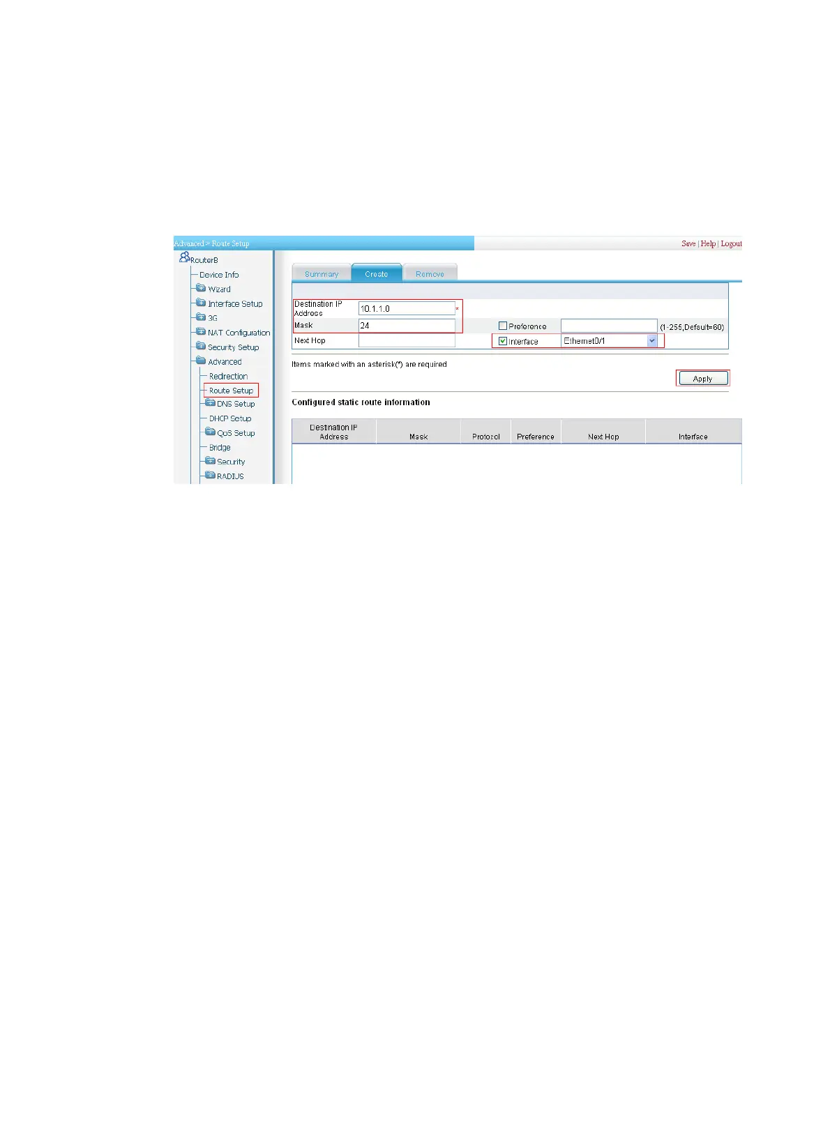
The page as shown in Figure 361 appears.
c. Enter 10.1.1.0 as the destination IP address.
d. Enter 24 as the mask.
e. Select Interface and then select Ethernet0/1 as the interface.
f. Click Apply.
Figure 361 Configuring a static route to Host A
3. Configure an IPsec connection.
a. Select VPN > IPsec VPN from the navigation tree.
b. Click Add to enter the IPsec connection configuration page (see Figure 360).
c. Enter map1 as the IPsec connection name.
d. Select interface Ethernet0/1.
e. Enter 2.2.2.1 as the remote gateway IP address.
f. Select the Pre-Shared-Key box, and then enter abcde in both the Key and Confirm Key fields.
g. In the Selector area, select the selector type Characteristics of Traffic.
h. Specify 10.1.2.0/0.0.0.255 as the source address/wildcard. Specify 10.1.1.0/0.0.0.255
as the destination address/wildcard.
i. Click Apply.
Verifying the configuration
After you complete the configuration, packets to be exchanged between subnet 10.1.1.0/24 and subnet
10.1.2.0/24 triggers the negotiation of SAs by IKE. After IKE negotiation succeeds and the IPsec SAs are
established, a static route to subnet 10.1.2.0/24 through 2.2.2.2 is added to the routing table on Device
A, and traffic between subnet 10.1.1.0/24 and subnet 10.1.2.0/24 is protected by IPsec.
Configuration guidelines
When you configure IPsec, follow these guidelines:
• Typically, IKE uses UDP port 500 for communication, and AH and ESP use the protocol numbers 51
and 50 respectively. Make sure flows of these protocols are not denied on the interfaces with IKE or
IPsec configured.

 Loading...