762
IVR configuration examples
Configure a secondary call on a call node (match the
terminator of numbers)
Network requirements
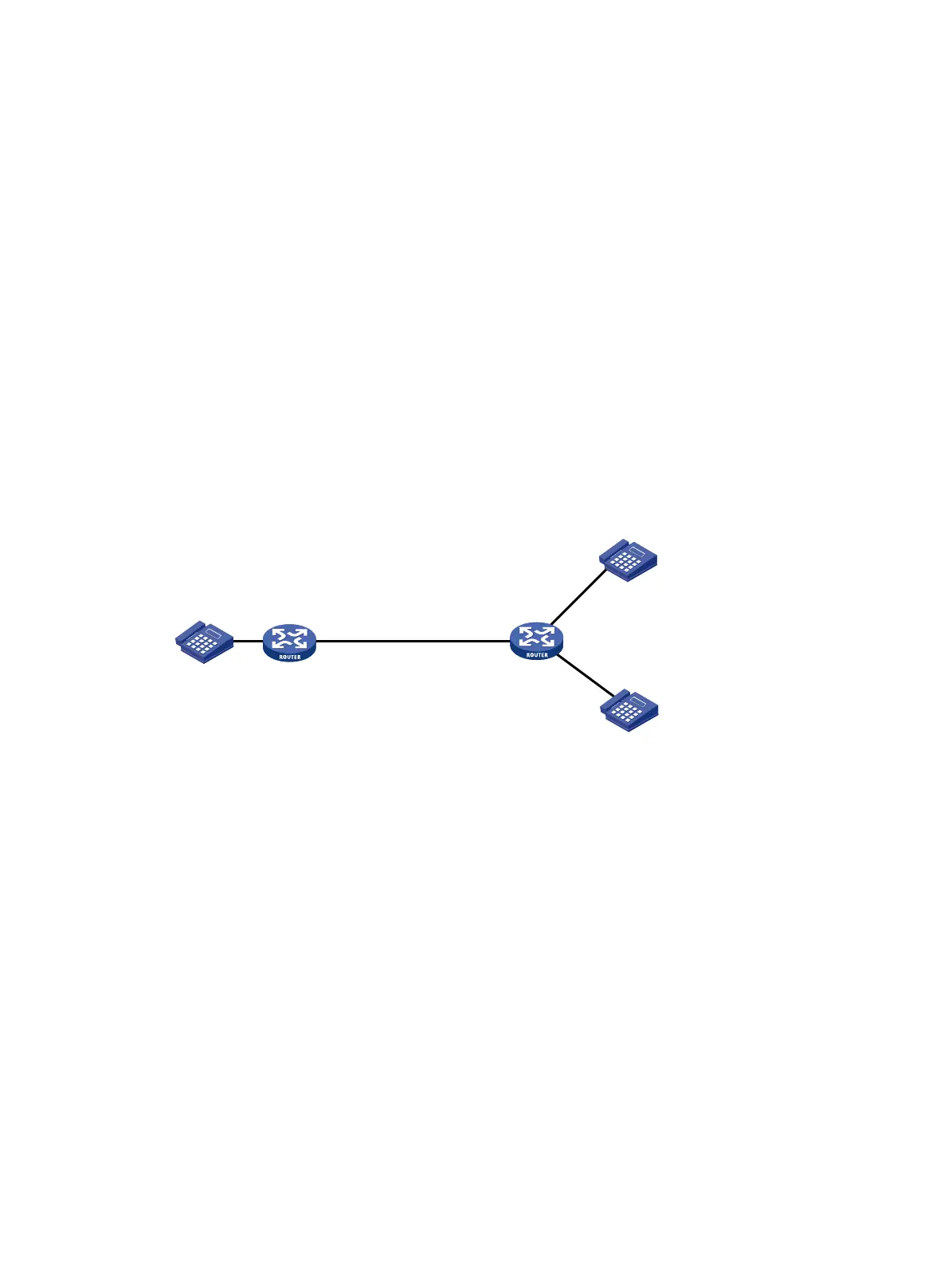
As shown in Figure 789, configure an IVR access number and call node functions on Router B to meet the
following requirements.
• After the subscriber dials 300 (the IVR access number) from Telephone A, Router B plays the audio
file welcome.wav.
• The subscriber dials 50# at Telephone A to originate a secondary call and then Telephone B1 rings.
• If the subscriber dials a wrong number at Telephone A, Router B plays the audio file
input_error.wav.
• If no number is dialed at Telephone A within the timeout time, Router B plays the audio file
timeout.wav.
Figure 789 Network diagram
Configuring Router A
# Configure a local number and call route.
1. Configure a local number in the local number configuration page: The number ID is 100, the
number is 100, and the bound line is line 1/0.
2. Configure a route to Router B in the call route configuration page: The route ID is 300; the
destination number is 300, the SIP routing method is IP routing, the destination IP address is
1.1.1.2, and the DTMF transmission mode is out-of-band.
Configuring Router B
# Configure local numbers in the local number configuration page:
• Local number 500: The number ID is 500, the number is 500, and the bound line is line 1/0.
• Local number 50: The number ID is 50, the number is 50, and the bound line is line 1/1.
# Upload g729r8 media resource files.
Select Voice Management > IVR Services > Media Resources Management from the navigation tree to
access the following page.
Telephone A
50
Eth1/1
1.1.1.1/24
Router A Router B
100
Eth1/1
1.1.1.2/24
Telephone B2
Telephone B1
500

 Loading...