245
3. Enter 2.1.1.100 in the End Address field.
4. Select interface Ethernet 1/1.
5. Enter 5 in the CIR field.
6. Select Per IP in the Type list.
7. Select Upload from the Direction list.
8. Click Apply.
Advanced queue configuration example
Network requirements
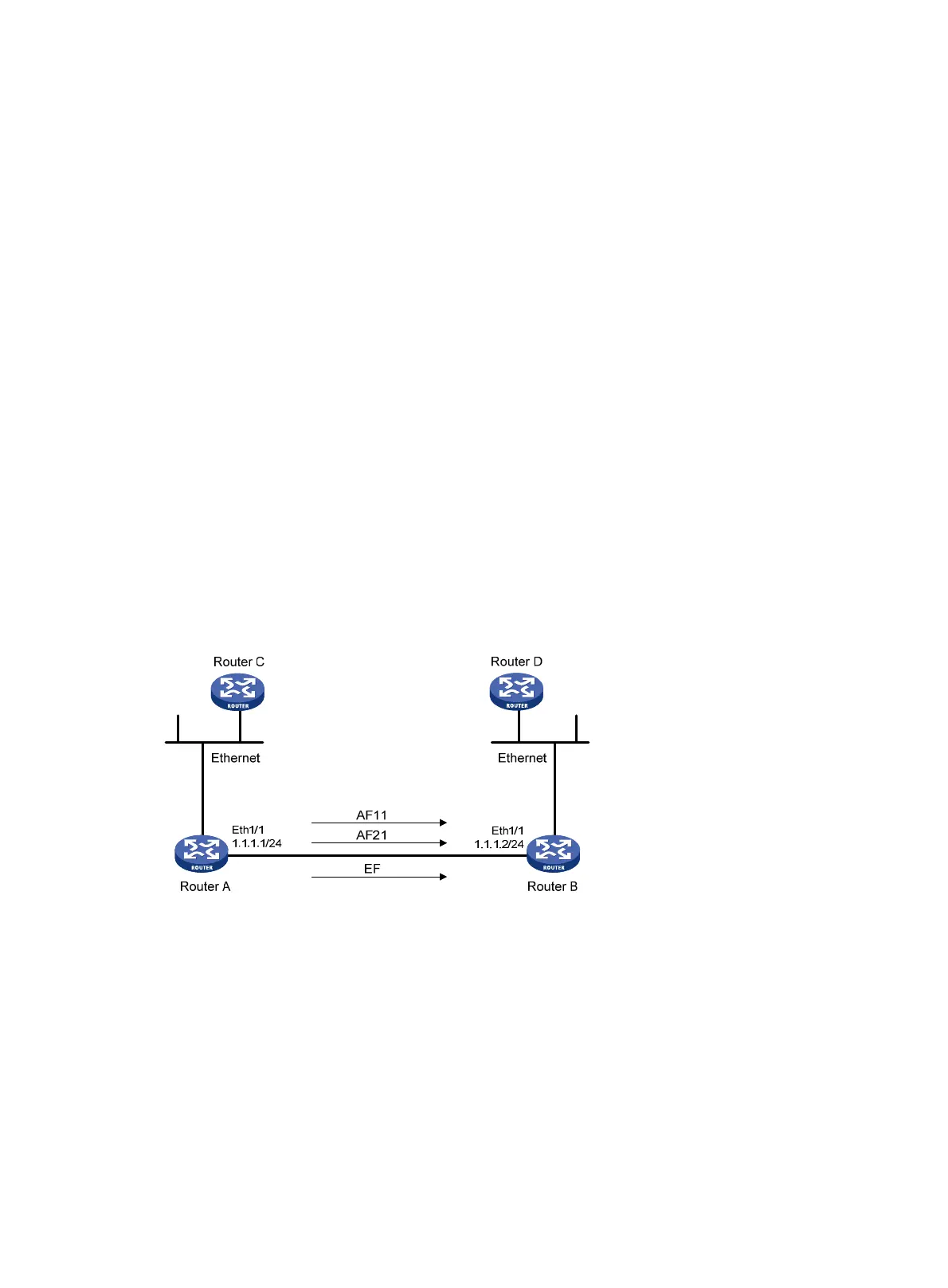
As shown in Figure 246, data traffic from Router C reaches Router D by the way of Router A and then
Router B. The data traffic from Router C is classified into three classes based on DSCP fields of IP packets.
Configure advanced queue to perform the following actions:
• Perform AF for traffic with the DSCP fields AF11 and AF22 (DSCP values 10 and 18), and set the
minimum bandwidth to 40 kbps.
• Perform EF for traffic with the DSCP field EF (DSCP value 46), and set the maximum bandwidth to
240 kbps.
Before performing the configuration, make sure:
• The route from Router C to Router D through Router A and Router B is reachable.
• The DSCP fields have been set for the traffic before the traffic enters Router A.
Figure 246 Network diagram
Configuration procedure
1. Configure Router A:
# Perform AF for traffic with DSCP fields AF11 and AF21.
a. Select Advance > QoS Setup > Advanced Queue from the navigation tree, and click Add on the
displayed page.

 Loading...