3: Installation of the SGX 5150
SGX 5150 IoT Device Gateway User Guide 24
Hardware Components
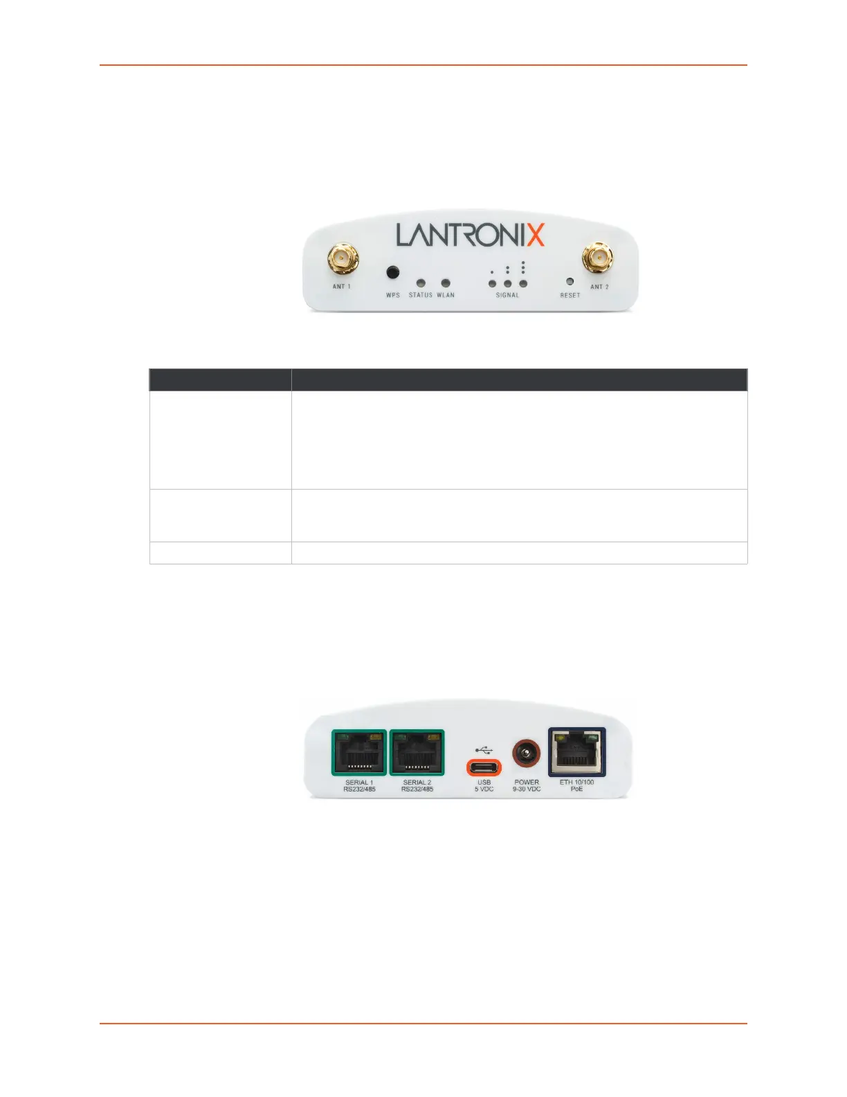
Front Panel
Figure 3-1 Front Panel
Table 3-2 SGX 5150 LEDs and Descriptions
Note: In Table 3-2 above, the L indicates a longer LED blink while the S indicates
shorter LED blink.
Back Panel
Figure 3-3 Back Panel
Serial Interface
One or two serial ports are available for the SGX 5150. Data rates can be configured for speeds
between 300 and 921 kbaud. Hardware protocol options include the following:
Two RJ45 RS232 Serial Ports, or
Two RJ45 Multi-protocol RS232/422/485 ports, or
One RJ45 RS232 Serial Port
Note: Multi-protocol ports come with configurable terminations 120 ohm on TX+/- and
RX+/-.
LED Description
Status No IP obtained from eth0 network: L, L, S, S, S
No IP obtained from wlan0 network: L, L, L, S, S, S
No IP obtained from the usb0 network: L, L, L, L, L, S
No eth0 link: L, L, S, S
No wlan link: L, L, L, S, S
No usb0 link: L, L, L, L, L, S, S
WLAN The wlan indicator light and color pattern indicates the wlan status according to
Table 3-11 and Table 3-12 and also reflects the WPS status according to
Table 3-14.
Signal See Table 3-11 and Table 3-12 for signal strength indication information.
 Loading...