3: Installation of the SGX 5150
SGX 5150 IoT Device Gateway User Guide 25
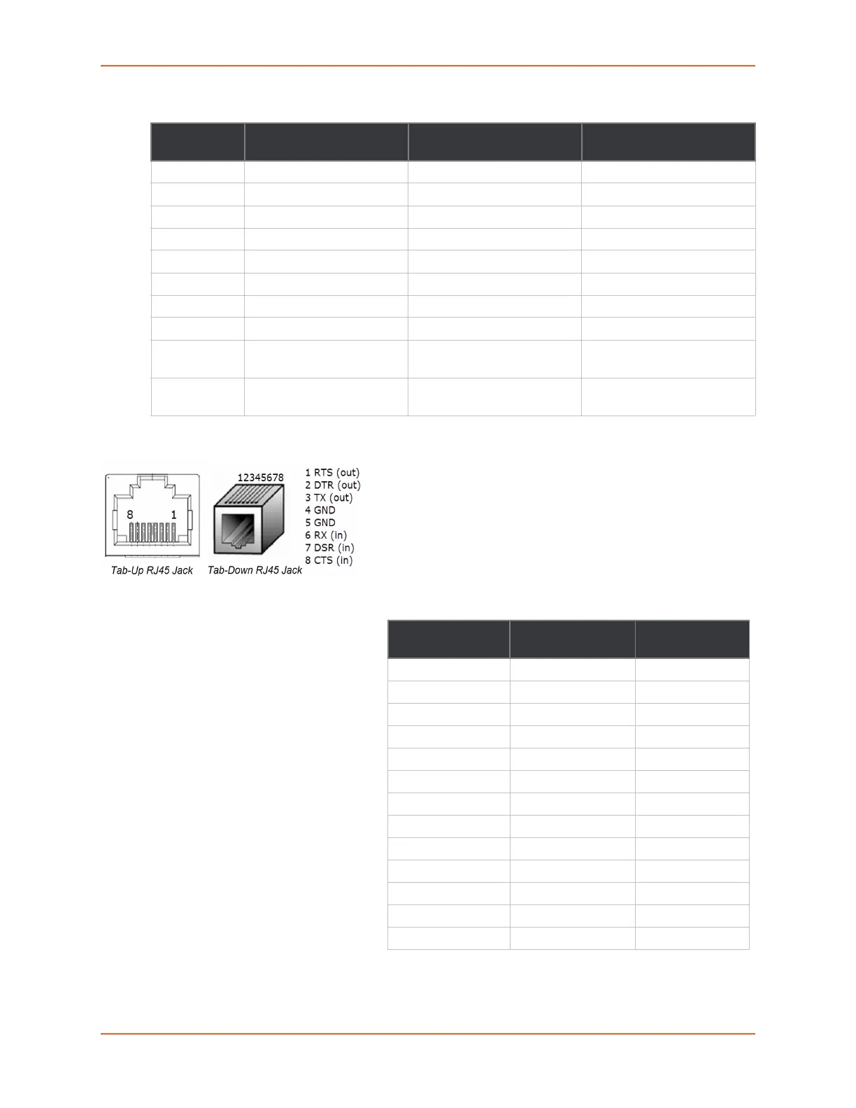
Table 3-4 Serial RJ45 Connector Pinout and LEDs
Note: For the proper operation of the RS422/485
4-wire, the 2-wire modes, as well as the RS232
mode, a GND (Ground) wire must be connected
between the equipment.
USB Connection
One USB 2.0 HS/FS port with
USB type C connector is
available on the SGX 5150 and
can be configured in two ways:
As a USB device (default
setting) where the SGX 5150
can be powered by a VBUS
5V.
As a USB configurable host
where the SGX 5150 can
provide VBUS 5V 0.5A if
powered by a Lantronix
provided wall adapter or PoE
(hardware optional).
Pin Number Signal Name for RS-232 Signal Name for
RS-422/485 (4 wire)
Signal Name for
RS485 2-Wire
1 RTS (output from SGX) TX+ (output from SGX) TX+/RX+
2 DTR (output from SGX) Not used/do not connect. Not used/do not connect
3 TXD (output from SGX) TX- (output from SGX) TX-/RX-
4 GND GND GND
5 GND GND GND
6 RXD (input to SGX) RX+ (input to SGX) Not used/do not connect
7 DCD (input to SGX) Not used/do not connect. Not used/do not connect
8 CTS (input to SGX) RX- (input to SGX) Not used/do not connect
Right LED Yellow for Transmit Data
activities (TXD)
Yellow for Transmit Data
activities (TXD)
Yellow for Transmit Data
activities (TX)
Left LED Green for Receive Data
activities (RXD)
Green for Receive Data
activities (RXD)
Green for Receive Data
activities (RX)
Figure 3-5 RJ45 Serial Port
Table 3-6 USB Type C Connector Pinout
Upper Row Pin
Number
Lower Row Pin
Number
Signal Name
A1 B1 Ground
A2 B2 No Connection
A3 B3 No Connection
A4 B4 VBUS 5V
A5 CC1
B5 CC2
A6 B6 Data+
A7 B7 Data-
A8 B8 No Connection
A9 B9 VBUS 5V
A10 B10 No Connection
A11 B11 No Connection
A12 B12 Ground
 Loading...