• To modify the non‑DTS key switches, cut the black/yellow stripe wire at each key switch and cover both open wire ends
with heat shrink tubing.
Typical key switch
a - Black/yellow stripe wire
IMPORTANT: The key switch at the station being used should be the only key switch in the run position. If both station key
switches are in the run position the engine cannot be turned off with the key switch and the lanyard stop switches will not
function.
• If a momentary stop switch is added, the stop switch will override the key switch and the engine will shut off when the stop
switch is activated.
• If a stop button is desired on a dual helm installation, the black wire and black/yellow stripe wire can be clipped at the key
switch and connected to a normally open momentary button switch. Any marine momentary push button, rocker style
switch or toggle switch could be utilized to create the stop switch. Label the switch on the dash after installation.
• To install a momentary stop switch:
a. Cut the black wire at the key switch and cover the cut wire at the key switch with heat shrink tubing.
b. Install an eye terminal on the black wire from the connector side. Cover cut wire ends with heat shrink tubing.
c. Install an eye terminal on the black/yellow stripe wire from the connector side. Cover cut wire ends with heat shrink
tubing.
d. Connect the black wire and the black/yellow stripe wire eye terminals to a momentary switch.
Typical key switch with momentary stop switch for MPI models
a - Black wire with eye terminals
b - Black/yellow stripe wire with eye terminals
c - Eye terminals connected to momentary switch
d - Momentary switch
Trim Switch
The trim switch connection on the helm harness is only used on Mercury outboard remote controls.
MerCruiser models require a separate trim harness from the trim control to the power trim pump connection. A Y‑harness is
available with adapters to connect the dual helm power trim harnesses together to connect to the transom harness. DTS
models do not need the separate trim harness.
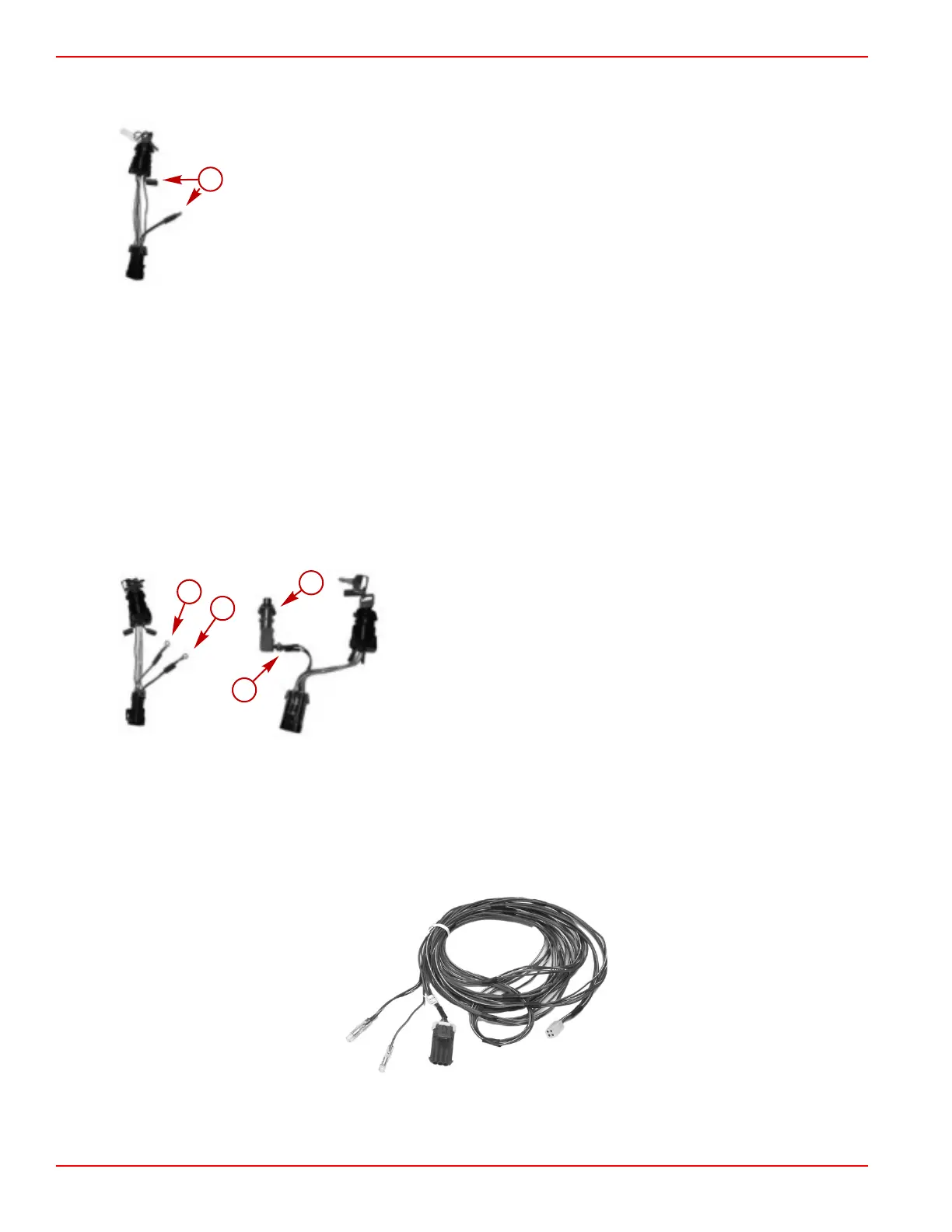
Use the power trim adapter harness for the single helm harness connection on the remote control to the power trim pump.
Power trim adapter harness
For dual helm installation, use a power trim extension harness from the upper and lower helm to a Y‑harness.
Installation
Page 2B-22 © 2016 Mercury Marine 90-8M0099748 eng DECEMBER 2015
 Loading...


