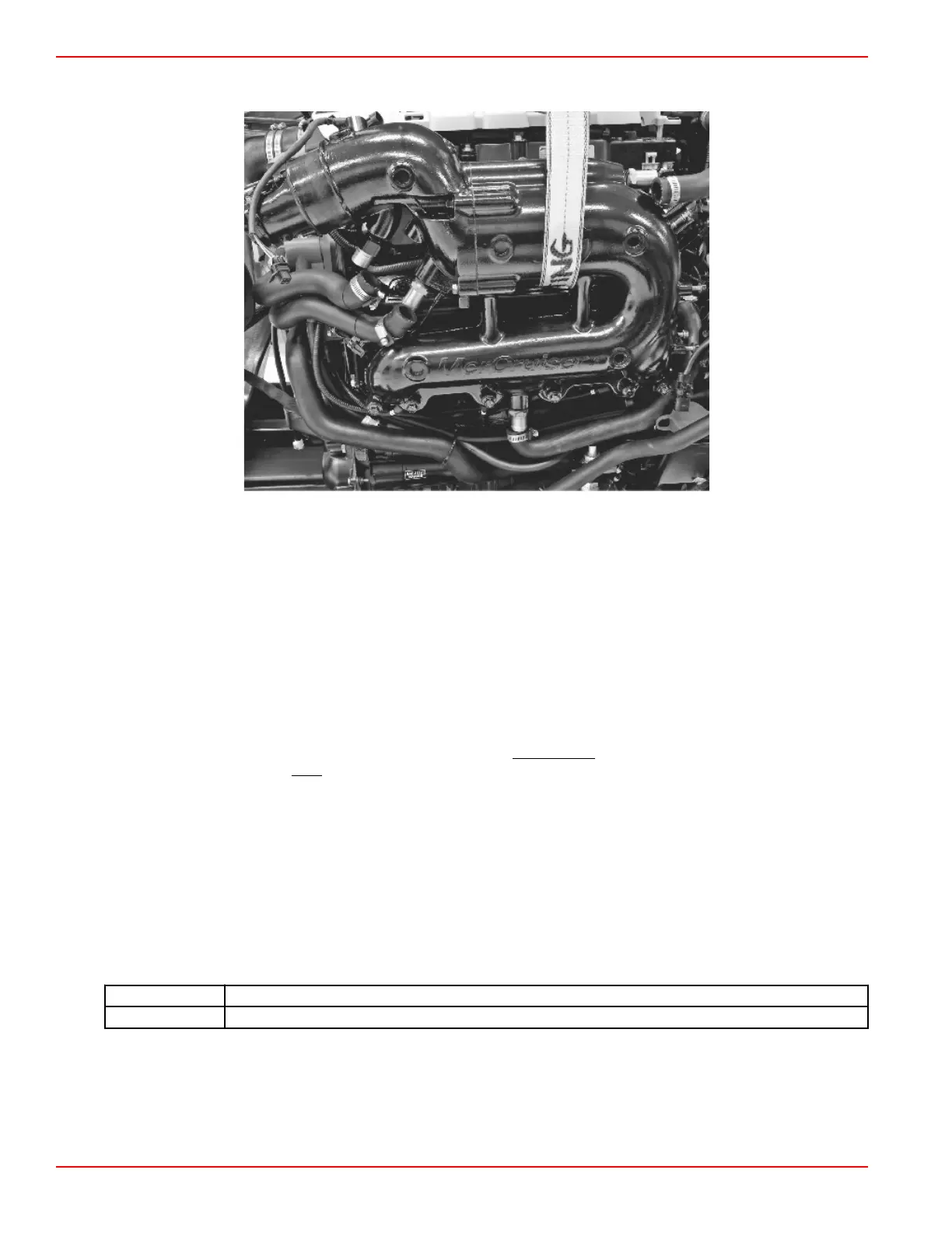
7. Route a suitable lifting strap through the exhaust manifold as shown. Attach the strap to a suitable hoist and raise the hoist
until all slack has been removed from the strap.
Lifting strap
8. Remove the two outer screws that secure the exhaust manifold.
9. Hand‑tighten two alignment pins (if available) in place of the removed screws.
10. Remove the four remaining screws.
• If alignment pins are not used, exercise special caution when removing the last screw, as the position of the manifold
may shift when the screw is removed.
• The tension on the lifting strap may need to be adjusted to prevent the manifold from slipping and causing injury or
damaging components (such as the spark plugs).
11. Remove the exhaust manifold and discard the gasket.
Manifold Cleaning and Inspection
IMPORTANT: This procedure is for the cleaning and inspection of the
manifold only. To perform the leak check within this
procedure, the elbow and catalyst must be removed. Refer to Exhaust Elbow Removal.
IMPORTANT: Exhaust gaskets are not reusable.
1. Clean any gasket material from all surfaces.
2. Check the water passages for foreign material. The passages must be clean for efficient cooling.
3. Inspect all parts for damage or wear. Repair or replace as necessary.
4. To test the exhaust manifold, use block‑off plates, plugs, or short hoses with plugged ends. One block‑off plate must have
a threaded hole for attaching a compressed air hose. Use new gaskets when installing block‑off plates. Apply 138 kPa
(20 psi) of air pressure and submerge the manifold in water. Air bubbles indicate a leak.
5. Inspect all sealing surfaces carefully. Machined surfaces must be clean and free of all marks and deep scratches or
exhaust leaks may result.
6. Ensure that all mating surfaces are flat.
Description
Maximum overall difference
Surface flatness 0.07 mm (0.003 in.) with not more than a 0.02 mm (0.001 in.) difference within 25 mm (1.0 in.)
NOTE: The maximum material that can be removed is 0.25 mm (0.01 in.) to flatten a gasket surface.
7. Inspect the condition of the metal around the exhaust outlet in the casting. Inspect for damage caused by saltwater or
exhaust gas corrosion in the manifold, elbow, and riser, if equipped. Replace all damaged parts.
Exhaust Manifold Installation
1. Ensure that the mating surfaces on the manifold and the cylinder head are clean and free from defects.
Manifolds and Elbows
Page 7B-12 © 2016 Mercury Marine 90-8M0099748 eng DECEMBER 2015
 Loading...


