System Link Gauges
System Link Gauge Connections
System Link gauges receive their data signal from a System gauge (System Monitor, System Tachometer, or VesselView) or
from a System Link adapter harness. This enables the use of System Link gauges in a variety of situations and configurations.
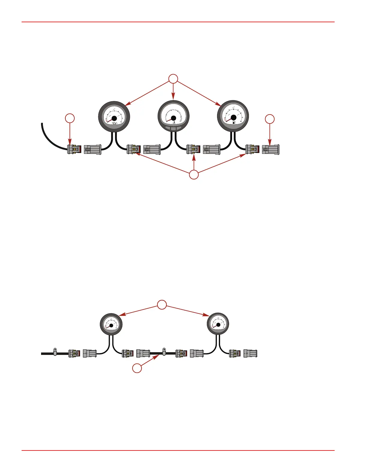
System Link gauges connect in series. Protect the System Link connector of the final gauge in a series with a weather cap.
Example System Link gauge setup
a - System Link connectors in series
b - System Link connector to master gauge
c - System Link gauges
d - Weather cap
Each set of System Link gauges monitors one engine. In multiple‑engine applications, install a System Link gauge set for each
engine. In all cases, the System Link gauges connect to a master gauge or System Link adapter harness, which is connected
to each engine's helm harness. For multiple‑helm applications, the secondary helm instrumentation connects to the secondary
helm harness in the same manner.
System Link Gauge Extension Harness Installation
The System Link gauge extension harness comes in five lengths, ranging from 15 cm to 9.1 m (6 in. to 30 ft). Install an
extension harness anywhere in the System Link gauge series if you require additional gauge spacing or an alternative gauge
mounting location. SmartCraft technology supports a System Link gauge series that does not exceed 9.1 m (30 ft) in overall
length. SmartCraft supports one and two‑helm installations with up to ten gauges per helm.
a - System Link gauge
extension harness
b - System Link gauge
Warning System
Service Engine Light and OBD‑M MIL Kit
Boats powered by emissions control technology (ECT) catalyzed engines must be equipped with a SmartCraft‑enabled gauge
capable of displaying the service engine icon, or a dash‑mounted service engine light. Malfunction indicator lamp (MIL) kits
containing a dash‑mounted service engine light and a special harness that connects to the engine harness may be purchased
separately.
0
1
OIL
4
1
2
3
4
1
0
50
TEMP
TROLL TROLL
+
-
MODE
100
150
200
F
o
0
1
FUEL
4
1
2
3
4
1
27544
b
c
a
d
Instrumentation and Controls
Page 4D-14 © 2016 Mercury Marine 90-8M0099748 eng DECEMBER 2015
 Loading...


