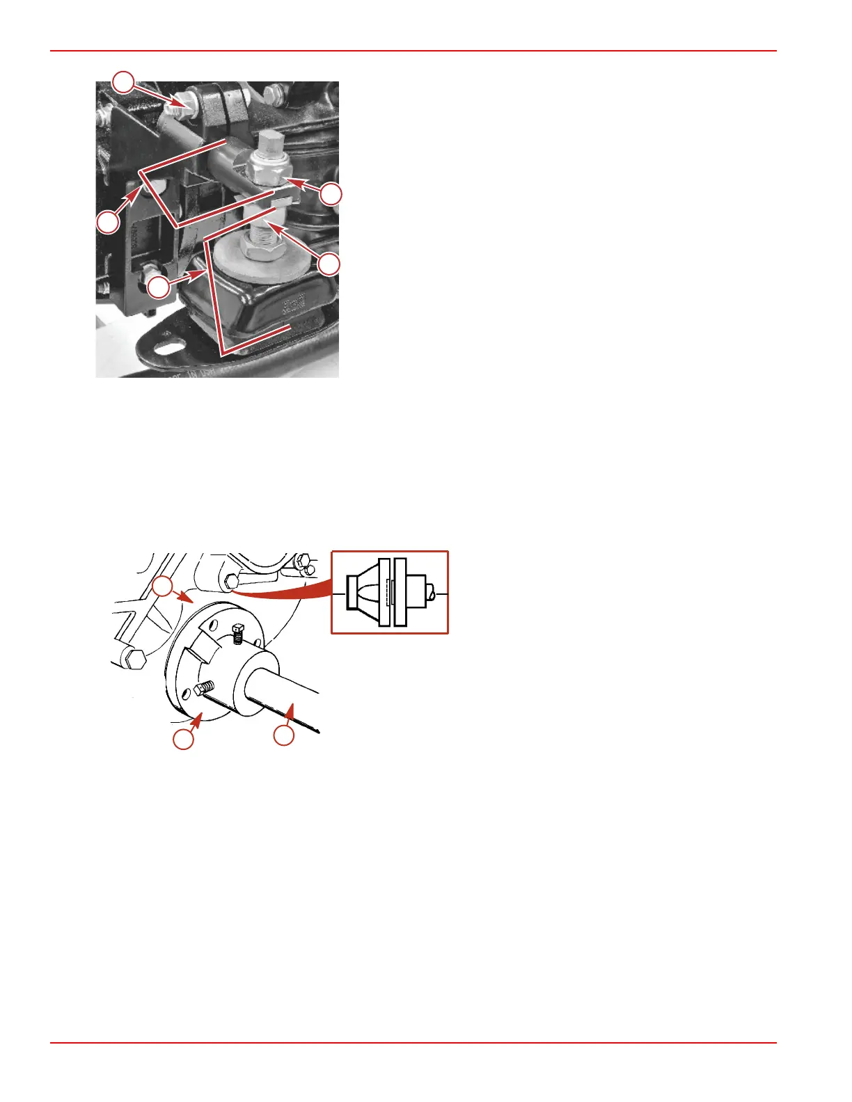
Typical rear mount
a - Locking nut
b - Adjusting nut
c - Trunnion clamp bolt and nut with lockwasher
d - 10 mm + 2 mm (3/8 in. + 1/16 in.)
e - 67 mm + 2 mm (2‑5/8 in. + 1/16 in.)
NOTE: Check the stringer for proper width for rear mount foot print.
Models with 8 Degree Down‑Angle Transmissions
1. Lift the engine into position in the boat using an overhead hoist.
2. Position the engine on the engine bed so that the transmission output flange and propeller shaft flange are aligned so that
no gap can be seen between flange coupling faces when they are butted together. Adjust the engine bed height if
necessary to obtain the proper alignment. Do NOT use the mount adjustments to adjust the engine position at this time.
IMPORTANT: The engine bed must position the engine so that a minimum of 6 mm (1/4 in.) up and down adjustment still
exists on all four mounts after performing initial alignment. This is necessary to allow for the final engine alignment.
a - Propeller shaft
b - Propeller shaft flange
c - Transmission output flange
3. Ensure that all four mounts are still positioned properly, then fasten the mounts to the engine bed with 10 mm (3/8 in.)
diameter lag bolts of sufficient length and flat washers. Tighten the lag bolts securely.
4. Ensure that the quick drain oil fitting is more than 13 mm (1/2 in.) above the boat bottom.
5. Disconnect the overhead hoist and remove the sling.
Models with V‑Drive Transmissions
1. Remove the engine cover.
2. Attach a suitable sling to the lifting eyes on the engine, and adjust it so that the engine is level when suspended.
3. Lift the engine into position in the boat using an overhead hoist.
4. Install a quick drain oil hose plug into the oil drain hose.
5. Position the engine so that enough of the propeller shaft protrudes through the transmission and output flange for the
propeller shaft flange to be attached. Then install the flange and position the engine so that no gap can be seen between
the flange coupling faces when butted together. Adjust the engine bed height if necessary to obtain the proper alignment.
Do not use the mount adjustments to adjust the engine position at this time.
b
c
a
7615
Installation
Page 2B-30 © 2016 Mercury Marine 90-8M0099748 eng DECEMBER 2015
 Loading...


