The use of both relay kits will result in a maximum of 80 amps of key controlled power at the helm. This multiplies out on dual
engine and dual helm applications as long as the power wires to the helm are adequate to carry the total current demand.
Accessory relay harness
CAN P (CAN 1) Connections
CAN P (CAN 1) data bus—Connection with a terminator resistor in place:
• The CAN P (CAN 1) data bus is terminated at each engine. Terminator resistors must be removed from the helm harness
or junction box and a jumper harness must be installed at the helm to connect the port and starboard CAN P (CAN 1) lines
together.
• If the boat is dual engine and dual helm, the terminator resistor at the lower helm is removed from the connector. The 2‑pin
link harness is installed at the upper station.
2-pin link harness—CAN
General Repower Information
• A 6‑pin fuel paddle boat harness is required.
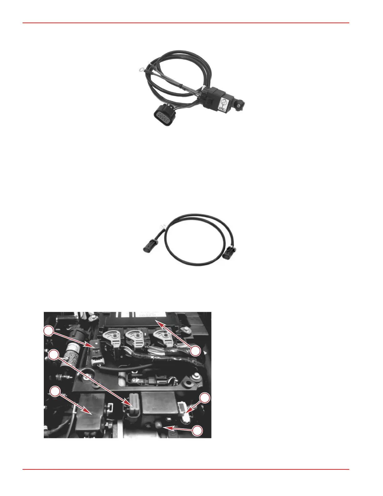
a - Can X terminator DTS only
b - 10‑pin diagnostics
c - Fuses
d - Circuit breaker
e - J1939 diagnostic connection
f - PCM 112
Installation
Page 2B-24 © 2016 Mercury Marine 90-8M0099748 eng DECEMBER 2015
 Loading...


