• Avoid sharp bends in exhaust hoses.
•
Exhaust hoses can be installed at up to a 5° angle relative to the exhaust elbow outlets. Refer to Exhaust Hose
Connections.
•
Exhaust elbows must be the prescribed distance above the waterline. Install risers if needed. Refer to Measuring Exhaust
Elbow Height.
• The exhaust hose attached to exhaust elbow must have a minimum of 10° downward slope.
• The exhaust hose must have a continuous downward slope so that a low spot does not exist at any point.
• Through‑hull exhaust fittings (flanges, outlets) must be equipped with internal shutters and external flappers to prevent the
reverse flow of water into the engine. Refer to Mercury MerCruiser Product Applications Manual.
• Exhaust outlets must be below the waterline with the boat at rest in the water and a full load aboard.
• Every exhaust hose connection should be secured with two hose clamps. The clamps should be stainless steel and at
least 13 mm (1/2 in.) wide. Clamps that rely solely on spring tension should not be used (ABYC Standard).
• The system must have the capability to be serviced, reassembled, and replaced while maintaining all of the specifications.
The boat builder must provide documentation, such as manuals, drawings, or orientation marks on production assemblies.
• Horizontal or vertical water lift mufflers are not permitted for use. Installers must use exhaust system provided with the
engine.
Exhaust System Guidelines—Inboard Models
These engines are equipped with a wet exhaust system in which exhaust is mixed with water in the exhaust elbows. This cools
the exhaust and allows the use of heat‑resistant rubber hose on the outlet side of the system. These specifications must be
observed by the OEM and muffler manufacturer when designing and installing the exhaust system:
• Heat‑resistant exhaust hose that complies with specifications SAE J2006 or UL 1129 should be used (ABYC standard).
• Exhaust hoses should be no smaller than the minimum sizes. Larger hoses should be used on applications with long hose
runs.
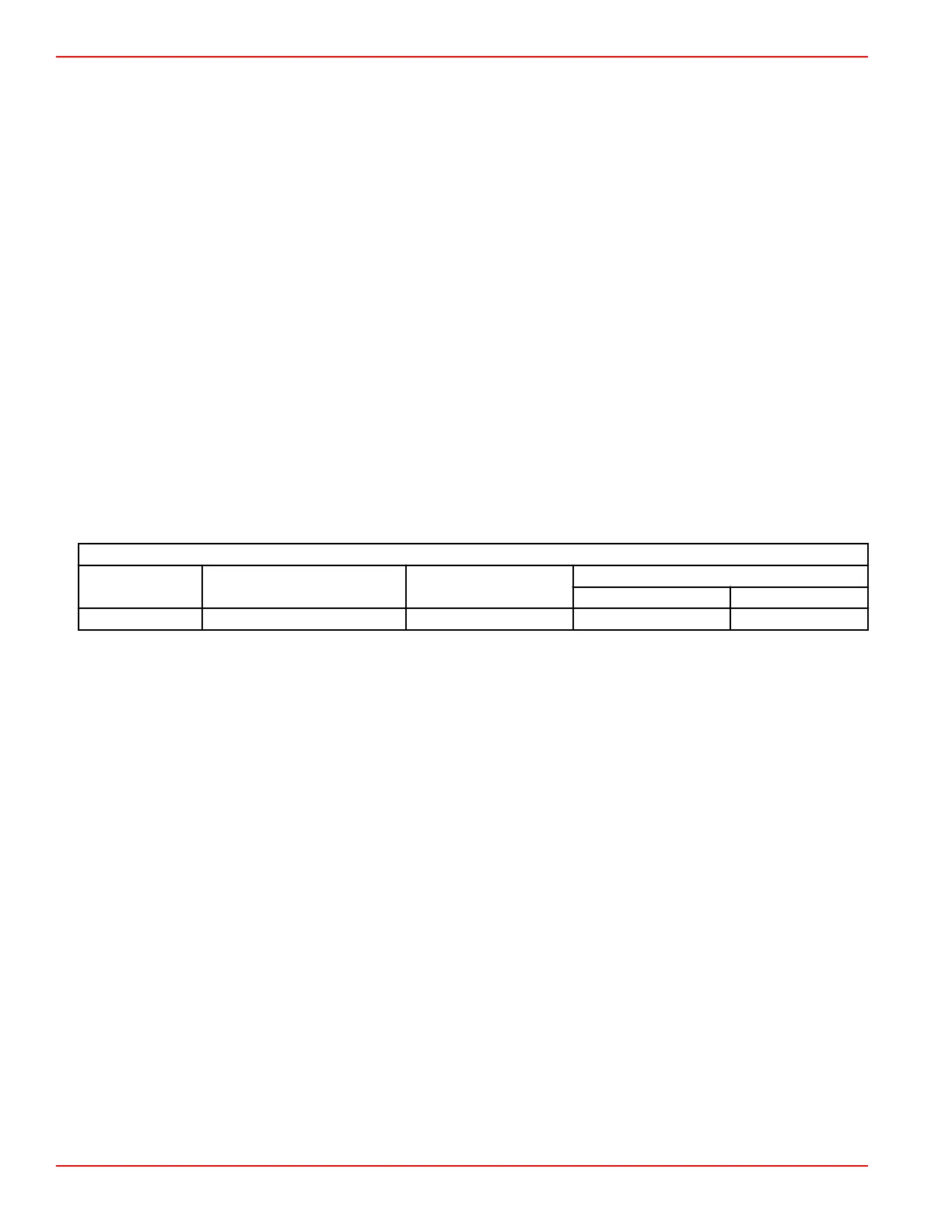
Minimum Exhaust Hose Size
Model Muffler Outlet Dual Outlet System
Single Outlet System
Dual Hose Portion Single Hose Portion
All Models 127 mm (5.0 in.) 102 mm (4 in.) 102 cm (4 in.) 102 mm (4 in.)
• Sharp bends in exhaust hoses should be avoided.
•
Exhaust hoses can be installed at up to a 5° angle relative to the exhaust elbow outlets. Refer to Exhaust Hose
Connections.
•
Exhaust elbows must be the prescribed distance above the waterline. Install risers if needed. Refer to Measuring Exhaust
Elbow Height.
• The exhaust hose attached to the exhaust elbow must have a minimum of 10° downward slope. On longer hose
applications, the slope can be reduced to 3° in the portion of exhaust system that is more than 457 mm (18 in.) away from
the elbow.
• The drop in the exhaust hose must be continuously sloping downward so that a low spot does not exist at any point.
• Through‑the‑hull exhaust fittings (flanges, outlets) must be equipped with internal shutters and idle relief to prevent the
reverse flow of water into the engine. Refer to Mercury MerCruiser Product Applications Manual.
• Idle relief hose should be 7.62 cm (3 in.) minimum diameter with the outlet above the waterline.
• Exhaust outlets must be below the waterline with the boat at rest in the water, and when the boat is underway with a full
load.
• Every exhaust hose connection should be secured with two hose clamps. The clamps should be stainless steel and at
least 13 mm (1/2 in.) wide. Clamps that rely solely on spring tension should not be used (ABYC Standard).
• The exhaust system must be adequately supported for proper orientation and to prevent overstressing the exhaust
manifolds and elbows. The support requirements will vary with exhaust system design and the G‑forces to be encountered.
•
The exhaust system must meet the exhaust back pressure specification. Refer to Mercury MerCruiser Product
Applications Manual
• The system must have the capability to be serviced, reassembled, and replaced while maintaining all of the specifications.
The boatbuilder must provide documentation, such as manuals, drawings, or orientation marks on production assemblies.
• If a waterlift or collector system is used, the waterline is defined as the waterline inside the collector. All measurements
must be taken from that waterline to measure exhaust elbow weight.
•
Horizontal waterlift mufflers are not permitted.
Installation
Page 2B-34 © 2016 Mercury Marine 90-8M0099748 eng DECEMBER 2015
 Loading...


