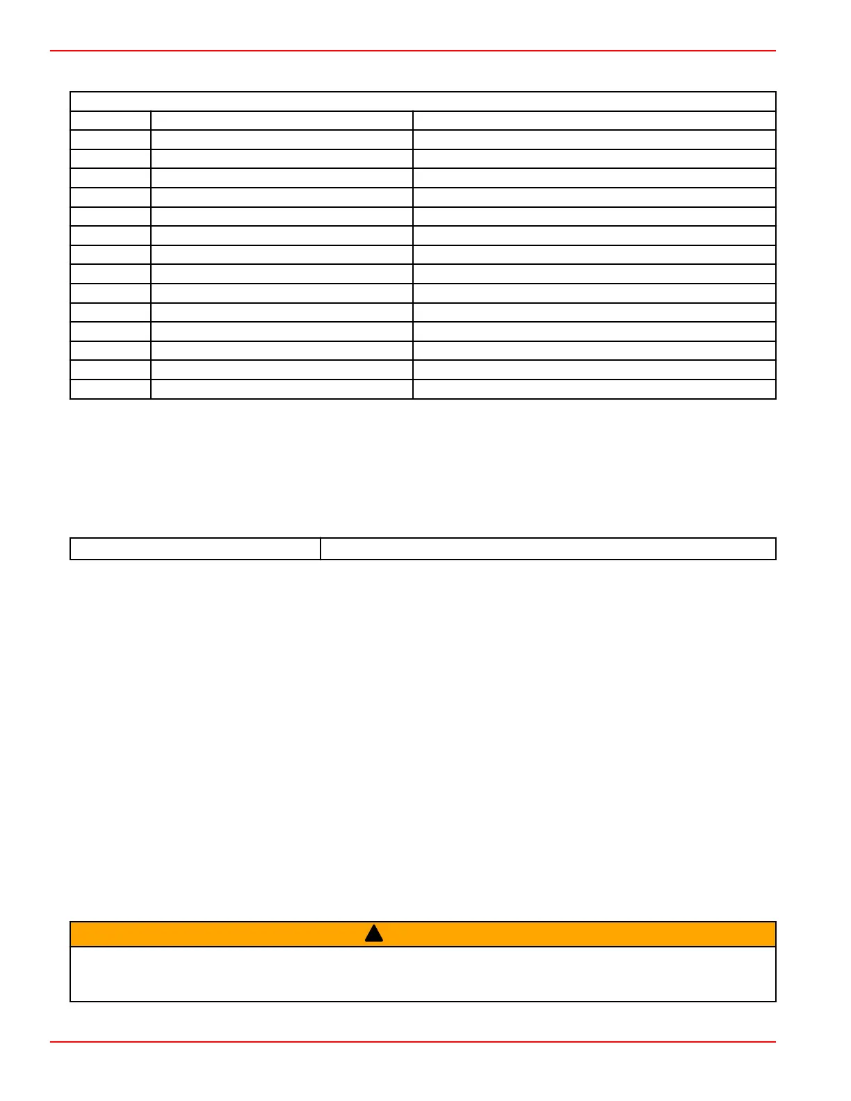
14‑Pin Engine Harness Connector
Mechanical 14‑Pin Connector Pin‑Out
Pin Wire Color Function
A Red/black Clean power
B Black Clean ground
C Purple Wake
D Black/yellow E‑stop
E Blue/yellow Oil pressure
F White CAN 1+
G Blue CAN 1–
H Blue/black Trim up
J Green/black Trim down
K Orange/green Trim gauge
L Tan/Lt blue Audio warning horn
M Gray Tachometer
N Yellow/red Crank
P Brown Temperature gauge
Axius Helm Installation (if Equipped)
If installing Axius, turn to Section 1 in the Axius Installation Manual and complete the appropriate procedures. Return here
when finished and complete any other appropriate procedures in this section.
DTS Information and Installation
Special Tools ‑ DTS Installation
Data Cable Puller
91‑888462A1
Configuring the PCM Using the CDS
The computer diagnostic system (CDS) can communicate with the DTS command module. However, the CDS will not
communicate with the PCM112 controller at this time. Refer to the following information when configuring the vessel or the
engine using the CDS tool.
Configuring the PCM
The computer diagnostic system (CDS) will not configure the following, which require communication through the propulsion
control module:
• Trailer and trim limit
• Engine location
• AutoSync‑Enable/Disable
• Use CDS G3 for configuring above
Configuring the DTS Command Module
The CDS G3 can configure the DTS command module. Refer to the appropriate procedures to configure the following:
• Vessel configuration
• Handle adaptation
• CAN‑based trackpad locations
Installation Guidelines for DTS System Components
!
WARNING
Splicing or probing will damage the wire insulation allowing water to enter the wiring. Water intrusion may lead to wiring
failure and loss of throttle and shift control. To avoid the possibility of serious injury or death from loss of boat control, do not
splice or probe into any wire insulation of the DTS system.
Instrumentation and Controls
Page 4D-26 © 2016 Mercury Marine 90-8M0099748 eng DECEMBER 2015
 Loading...


