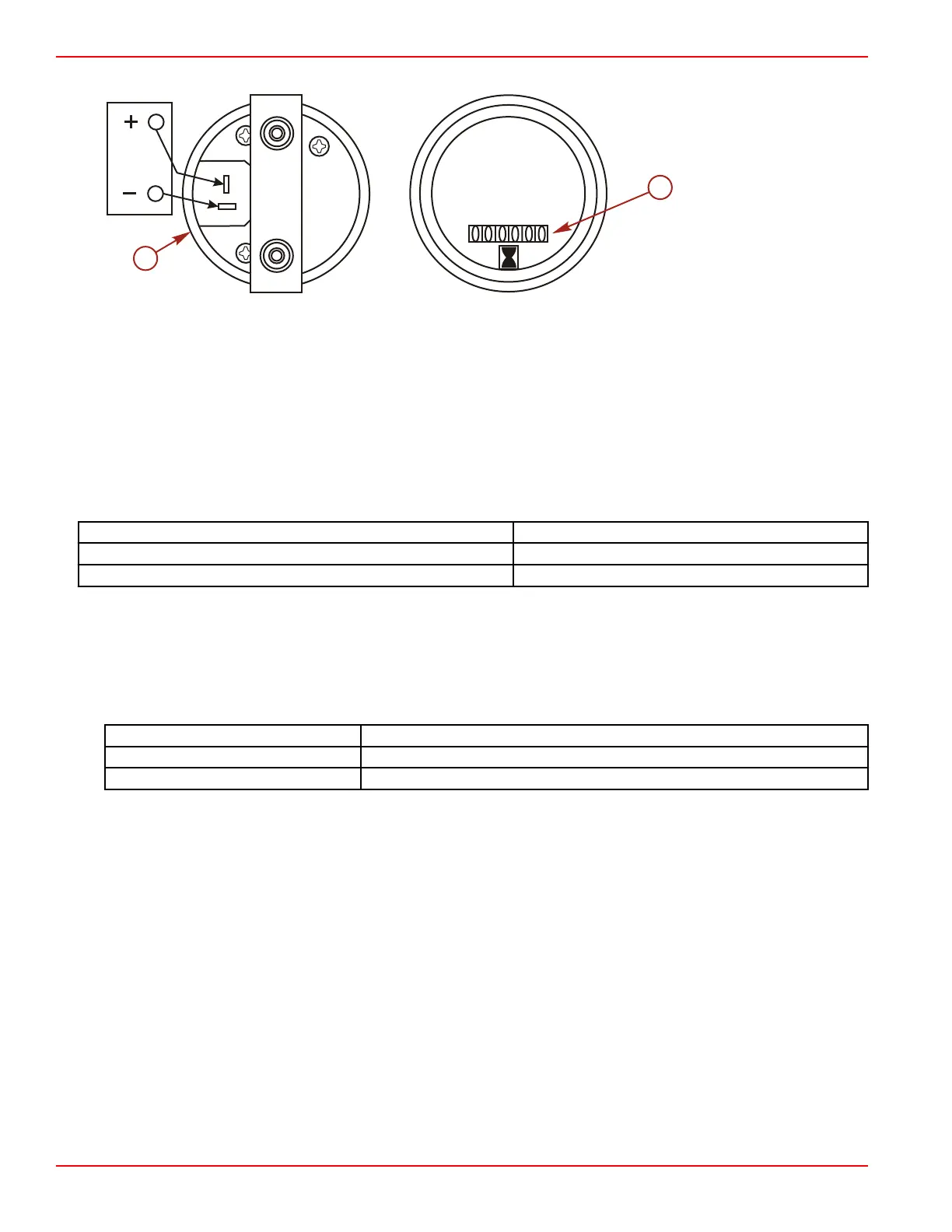
3. Connect a positive (+) jumper lead from the battery to gauge terminal + (12 V).
a - Electrical connections
b - Display
4. Connect a negative (–) jumper lead from the battery to gauge terminal "GND" (ground) or "–" (negative, or ground).
5. If the indicator display is not turning, the gauge is inoperable. Replace the gauge.
Tachometer
IMPORTANT: Ensure that the pulses per revolution selector on the back of the tachometer is set to 4.
1. Connect a service tachometer to the engine and compare readings between the service tachometer and the helm
tachometer.
2. If the gauge is not accurate, make sure that the switch on the rear of the tachometer is set properly. Refer to the
manufacturer's instructions that accompanied the gauge for an explanation of selections.
3. If the gauge does not meet the specifications, replace the gauge.
Tachometer Type
Allowable Range
5000 RPM maximum ± 100 RPM
6000 RPM maximum ± 150 RPM
Speedometer
IMPORTANT: When testing the speedometer for accuracy, the air supply used for the test must be regulated to the specified
air pressure. Do not apply excessive air pressure.
1. Supply the specified air pressure to the speedometer gauge pitot tube and compare the gauge readings to the
specification. Lightly tap the pressure gauge during the accuracy check.
2. If the gauge readings are not within specifications, replace the gauge.
Air pressure
Speedometer display
36.5 kPa (5.3 psi) 32 km/h ± 1.6 km/h (20 mph ± 1 mph)
192 kPa (27.8 psi) 72 km/h ± 1.6 km/h (45 mph ± 1 mph)
SmartCraft Instrumentation
SmartCraft Compatibility
IMPORTANT: Digital gauges are available for use on Mercury MerCruiser engines equipped with the ECM 555 or later model
controllers.
All System Series instruments are compatible with MerCruiser products.
• SC1000 System Monitor
• SC1000 System Tachometer and Speedometer
• SC100 System Link Gauges
Refer to the Mercury SmartCraft Operation Manual for information on the setup and operation of the System Monitor, System
Tachometer, and System Speedometer.
SmartCraft System Rules
Controller area network (CAN) data bus wiring rules are the same for all SmartCraft compatible products.
• There are two termination resistors per CAN.
• Termination resistors define the ends of the CAN bus trunk.
• The maximum allowable CAN bus trunk cable length is 36.6 m (120 ft).
• Drops from the trunk should not exceed 1.8 m (6.0 ft).
Instrumentation and Controls
Page 4D-6 © 2016 Mercury Marine 90-8M0099748 eng DECEMBER 2015

 Loading...


