1. Do the first step torque on the rear main bearing cap.
Description Nm lb‑in. lb‑ft
Crankshaft (main) bearing cap bolt—preferred method
First torque
25 – 18.4
2. Using a lead hammer, tap the end of the crankshaft to the rear.
3. Using a lead hammer, tap the end of the crankshaft to the front.
4. Do the final step torque on the bearing cap.
Description Nm lb‑in. lb‑ft
Crankshaft (main) bearing cap bolt—preferred method
Final torque
+90°
Valves and Seals (Without Removing Head)
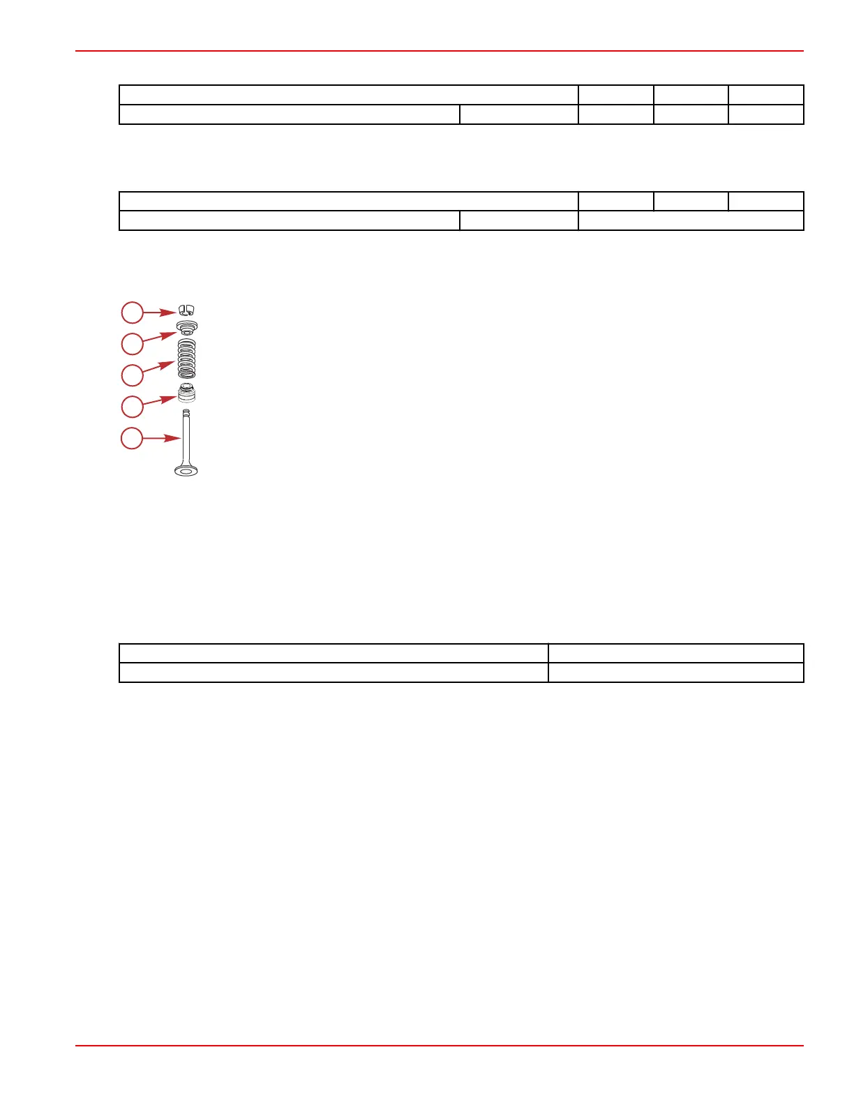
Valve Spring Assembly Exploded View
a - Valve
b - Valve stem oil seal
c - Valve spring
d - Valve spring retainer
e - Valve spring lock
Valve Spring Assembly Removal
1. Remove the rocker arm cover.
2. Remove the spark plug of the cylinder being serviced.
3. Remove the rocker arm assembly.
IMPORTANT: Keep air pressure in the cylinder while springs, caps, and valve locks are removed or the valves will fall into
the cylinder.
4. Install a spark plug port adapter in the spark plug hole and apply 138–206 kPa (20–30 psi) of compressed air to hold the
valves in place.
Description
SPX Part Number
Spark plug port adapter J23590
NOTE: If compressed air is not available, the piston may be brought up to TDC to keep the valves from falling out of the
cylinder head.
Engine Inspection and Assembly
90-8M0099748 eng DECEMBER 2015 © 2016 Mercury Marine Page 3B-69
 Loading...


