Special Tools
Data Cable Puller 91‑888462A1
4618
Attaches to end of DTS data harness to aid in pulling harness through boat.
Prevents damage to DTS data harness.
Configuring the PCM Tachometer Signal (Non‑DTS)
IMPORTANT: The engine propulsion control module (PCM) tachometer factory default is set to analog. This allows the
operation of one analog tachometer. The PCM can be configured for digital output for applications utilizing an analog gauge
interface (AGI) or digital gauges.
Use the Computer Diagnostic System (CDS) G3 to configure PCM tachometer output.
Gauge Configuration
Analog Digital
Analog Tachometer Only
X
System Link gauges used with VesselView, System Monitor, or System Tach
leave at factory setting
System Link gauges used in conjunction with System Link adapter harness and command module
harness without the use of VesselView, System Monitor, or System Tach
X
AGI used with or without VesselView, System Monitor or System Tachometer, to run analog and
System Link gauges
X
Cleaning the Gauges
Clean the gauge by washing the face of the gauge and the trim ring with fresh water to remove sand and salt deposits. Wipe off
the gauge face and trim ring with a soft cloth moistened with water. The gauge can be scored or damaged if wiped with
abrasive material (for example, sand, saline, or detergent compounds) or washed with solvents such as trichloroethylene or
turpentine.
Analog Gauges
Gauge Lighting Options
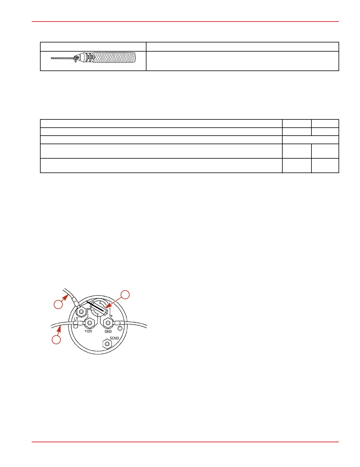
Some gauges (Admiral and Flagship series) are equipped with two bulb socket settings for optional lighting configurations. The
light bulb socket can be removed and the contacts can be aligned to be used with an ignition switch lighting circuit (+12 V) or a
separate instrumentation lighting circuit (LT).
The standard position is instrumentation lighting circuit (LT) for use with the separate panel lights and audio test switch.
IMPORTANT: To adjust the lighting option to the desired setting, you must remove the light socket from the gauge and then
turn it. Turning the socket while it is installed in the gauge could result in damage to the gauge or socket.
a - Light socket
b - +12 V power supply from the panel lights and audio test switch
c - +12 V power supply from the ignition switch
Removal
1. Disconnect the battery cables. Remove the negative (–) cable first.
2. Remove the wires from the back of the gauge.
3. Disconnect the light socket wiring, if separate.
4. Remove the holding strap or unscrew the mounting ring around the gauge, and remove the gauge.
Installation
1. Position the gauge assembly in the appropriate mounting hole.
IMPORTANT: Do not distort the case or bracket by overtightening.
b
13553
c
a
Instrumentation and Controls
90-8M0099748 eng DECEMBER 2015 © 2016 Mercury Marine Page 4D-3
 Loading...


