NOTE: If clearance cannot be brought to within specifications, the crankshaft connecting rod journal will have to be ground
undersized. If the connecting rod journal is already at maximum undersized, replace the crankshaft.
9. Coat the selected bearing surface with oil.
10. Install the connecting rod cap.
11. Tighten the bearing cap screws in two steps to the specified torque.
Description Nm lb‑in. lb‑ft
Bearing cap screws
First torque
25 – 18.4
Final
+90°
Oil Pump
Inspection
IMPORTANT: Pump gears and body are not serviced separately. If the pump gears or body are damaged or worn, replacement
of the entire oil pump assembly is necessary.
1. Inspect the pump body and cover for cracks or excessive wear.
2. Inspect the pump gears for damage and excessive wear, such as chipped teeth and galling.
3. Check the gear shafts in the pump body for galling, scoring, or excessive shaft‑to‑bore clearance.
4. Inspect the inside of the pump cover for wear that would permit oil to leak past the gears.
5. Inspect the pickup screen and suction pipe assembly for damage or blockage.
6. Check the pressure regulator valve for smooth, nonbinding fit in its bore in the oil pump cover.
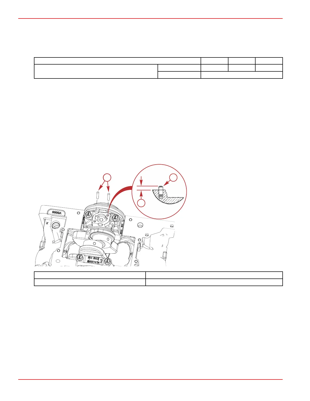
7. Inspect the oil pump locator dowel pins for damage and proper height.
a - Dowel pins
b - Oil pump dowel pin height
Description Height
Oil pump dowel pin 8.067–9.683 mm (0.3175–0.3812 in.)
Installation
1. Align the oil pump driveshaft with the intermediate shaft.
Engine Inspection and Assembly
Page 3B-32 © 2016 Mercury Marine 90-8M0099748 eng DECEMBER 2015
 Loading...


