EasyManua.ls Logo

Omron CP1H CPU User Manual

Omron CP1H CPU
788 pages
To Next Page IconTo Next Page
To Previous Page IconTo Previous Page
Page #116 background imageLoading...
Page #116 background image
82
CPU Unit Operation Section 2-4
2-4 CPU Unit Operation
2-4-1 General Flow
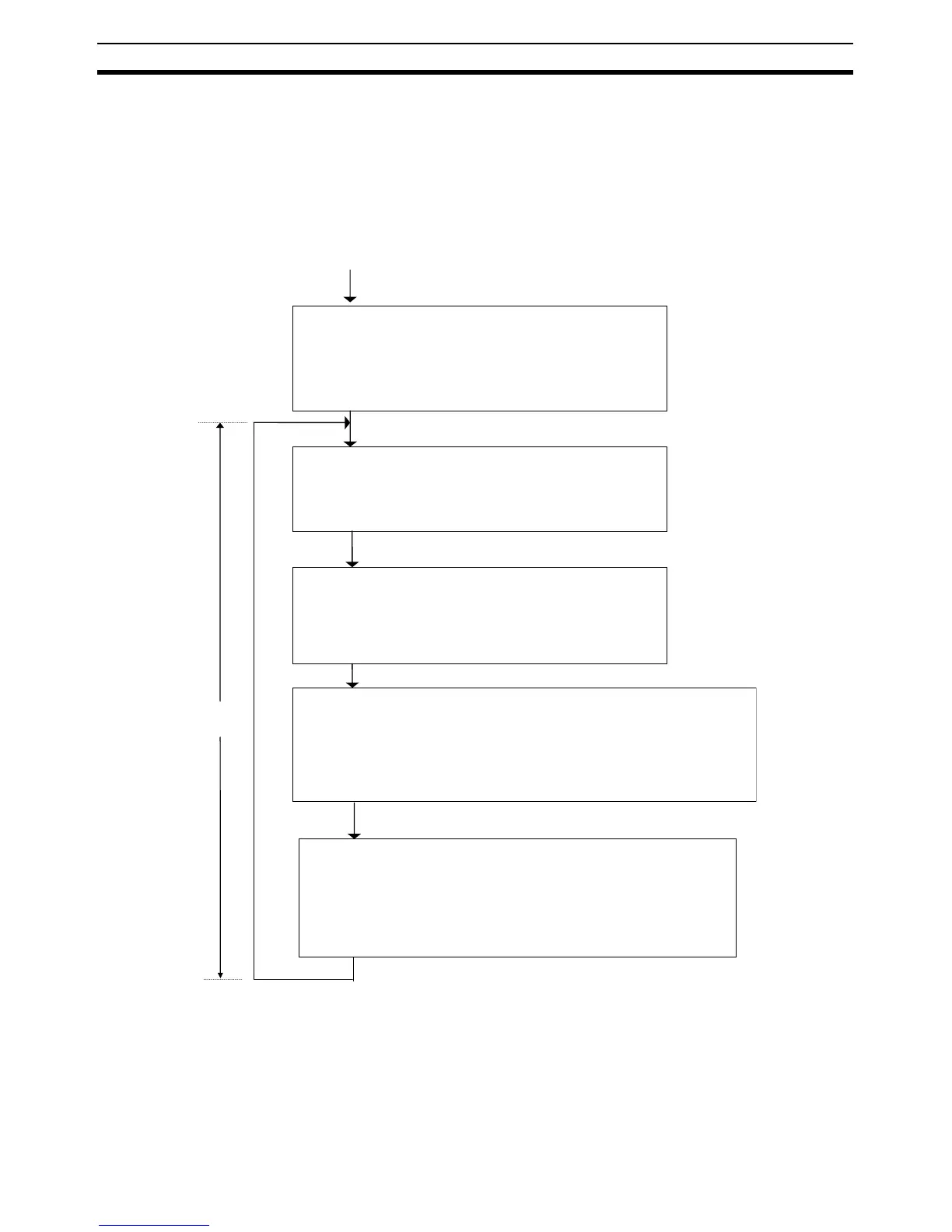
The following flowchart shows the overall operation of the CPU Unit. First the
user program is executed and then I/O is refreshed and peripheral servicing is
performed. These processes are then repeated in cyclic fashion.
Startup
initialization
I/O refreshing
(even in
PROGRAM
mode)
Peripheral
servicing
Cycle time
Initialize hardware
memory and system work
area.
Detect I/O.
Automatically transfer data
from Memory Cassette.
Clear I/O memory.
Check user memory.
Clear forced status, etc.
Check the Battery.
Read DIP switch settings.
Check I/O bus.
Check user program
memory.
Overseeing
processing
Program
execution
Operation processing: Execute the user program.
Error processing: Turn OFF outputs. (Reset Units
for bus errors.)
After error: Clear I/O memory if an error occurs
(unless a FALS(007) instruction created the error).
Refresh data for the following Units.
CP-series Expansion Units and Expansion I/O Units
CJ-series Special I/O Units (both words allocated in CIO Area and
specific data for each Unit)
CJ-series CPU Bus Units (both words allocated in CIO and DM Areas
and specific data for each Unit)
Perform the following servicing if any events have occurred.
CJ-series Special I/O Unit event servicing
CJ-series CPU Bus Unit event servicing
Peripheral USB port servicing
Serial port servicing
Communications port servicing
Built-in flash memory access servicing
Memory Cassette access servicing
Power ON

Table of Contents

Questions and Answers:

Omron CP1H CPU Specifications

General IconGeneral
PLC SeriesCP1H
Program Memory20K steps
Data Memory32K words
High-speed counters4 (up to 100 kHz)
Pulse outputs4 (up to 100 kHz)
Analog OutputsUp to 2
Expansion Slots3
Operating Temperature0 to 55 °C
I/O PointsVaries by model. See details below.
High-speed Counter100 kHz
Pulse Output100 kHz
Analog InputsVaries by model. See details below.
Communication PortsRS-232C
Programming LanguageLadder logic, Structured text
Power Supply24 VDC

Summary

OPERATION MANUAL

SYSMAC CP Series

Overview of the SYSMAC CP Series, including its features and basic specifications.

CP1H CPU Unit

Details on the CP1H CPU Unit, its models, and capabilities.

PRECAUTIONS

Intended Audience

Identifies the target personnel for this manual, requiring knowledge of electrical systems.

General Precautions

General guidelines for operating the product according to specifications and consulting representatives.

Safety Precautions

Critical safety warnings regarding handling the unit, power supply, and external circuits.

Operating Environment Precautions

Guidelines for installing and operating the PLC in suitable environmental conditions.

Application Precautions

Precautions for using the PLC system safely and preventing faulty operation or damage.

Conformance to EC Directives

Information on compliance with EC Directives, including EMC and Low Voltage Directives.

SECTION 1 Features and System Configuration

Features and Main Functions

Introduces the features and main functions of the CP1H and available units.

System Configuration

Describes the system configuration, including basic setup and expansion capabilities.

Connecting Programming Devices

Explains how to connect programming devices to the CP1H via USB or serial ports.

SECTION 2 Nomenclature and Specifications

Part Names and Functions

Identifies and describes the various parts and functions of the CP1H CPU Units.

Specifications

Provides detailed technical specifications for CP1H CPU Units, including electrical and environmental data.

SECTION 3 Installation and Wiring

Installation Precautions

Important considerations for safe and reliable installation of the PLC, including ambient conditions.

Mounting

Details the procedures for mounting the CP1H CPU Unit and expansion units in a panel or on a DIN track.

Wiring CP1H CPU Units

Provides instructions on wiring the power supply, ground lines, and built-in I/O for CP1H CPU Units.

SECTION 4 I/O Memory Allocation

Overview of I/O Memory Area

Describes the structure and functions of the I/O memory areas, including CIO, Work, Holding, and Auxiliary Areas.

I/O Area and I/O Allocations

Explains the I/O area structure and how I/O points are allocated for built-in and expansion units.

SECTION 5 Basic CP1H Functions

Interrupt Functions

Explains the different types of interrupt functions available, including input, scheduled, and high-speed counter interrupts.

High-speed Counters

Details the specifications, procedures, and settings for high-speed counter operations.

Pulse Outputs

Covers the functions, specifications, and patterns for pulse outputs used in positioning and speed control.

SECTION 6 Advanced Functions

Serial Communications

Describes the serial communication functions supported by CP1H CPU Units, including protocols and connections.

Program Protection

Explains functions for protecting the user program from unauthorized access, including read and write protection.

Failure Diagnosis Functions

Covers functions for diagnosing failures, including alarm instructions, failure point detection, and simulating system errors.

SECTION 7 Using CP-series Expansion Units and Expansion I/O Units

Connecting CP-series Expansion Units and Expansion I/O Units

Details the procedure for connecting CP-series Expansion Units and Expansion I/O Units to the CP1H.

Analog Input Units

Describes the specifications and wiring for CPM1A-MAD01/CP1W-MAD11 Analog Input Units.

Analog Output Units

Details the specifications and wiring for CP1W-DA041/CPM1A-DA041 Analog Output Units.

SECTION 8 LCD Option Board

Features

Outlines the features of the LCD Option Board, including its display and setting capabilities.

Installation and Removing

Explains the procedure for installing and removing the LCD Option Board from the PLC.

Basic Operation

Covers the startup screens, screen transitions, and operation examples of the LCD Option Board.

LCD Option Board Function

Describes the functions of the LCD Option Board for monitoring and settings, including PLC mode and I/O memory.

SECTION 9 Ethernet Option Board

Ethernet Option Board Function Guide

Provides an overview of the Ethernet Option Board's functions, system configuration, and specifications.

System Configuration

Details the system configuration for constructing an Ethernet network and required devices.

Installation and Initial Setup

Explains the procedure for installing and performing the initial setup of the Ethernet Option Board.

Trouble Shooting

Lists errors during operation and provides countermeasures for the Ethernet Option Board.

SECTION 10 Program Transfer, Trial Operation, and Debugging

Program Transfer

Describes the process of transferring programs, PLC setup, and I/O memory data to the CPU Unit.

Trial Operation and Debugging

Covers functions for trial operation and debugging, including forced set/reset and online editing.

SECTION 11 Troubleshooting

Error Classification and Confirmation

Classifies errors into categories (CPU, fatal, non-fatal) and explains how to confirm them using indicators and displays.

Troubleshooting

Provides procedures for checking error details and removing causes, covering symptoms like no operation or communication errors.

SECTION 12 Inspection and Maintenance

Inspections

Details daily or periodic inspections required to maintain PLC functions in peak operating condition.

Unit Replacement Precautions

Important precautions to follow when replacing a faulty Unit, such as ensuring power is OFF.

Replacing User-serviceable Parts

Describes the procedure for periodically replacing parts like the battery for preventative maintenance.

Appendix A Standard Models

CPU Units

Lists the standard models of CP1H CPU Units, including specifications and remarks.

Programming Devices

Lists the recommended programming devices, such as CX-Programmer, and their applications.

Optional Products

Lists optional products like Option Boards, Memory Cassettes, and CJ Unit Adapters.

Appendix B Dimensions Diagrams

X, XA, and Y CPU Units

Provides the physical dimensions and mounting details for the CP1H CPU Units.

Optional Products CP1W-CIF01/CIF11/CIF12 Option Boards

Shows the dimensions and specifications of serial communication option boards.

CP1W-DAM01 LCD Option Board

Displays the dimensions and part names of the LCD Option Board.

CP1W-CIF41 Ethernet Option Board

Provides the dimensions and specifications of the Ethernet Option Board.

CP1W-ME05M Memory Cassette

Shows the dimensions of the Memory Cassette.

Expansion I/O Units

Provides the dimensions for various CP-series Expansion I/O Units.

Appendix C Auxiliary Area Allocations by Function

Initial Settings

Describes initial settings for IOM Hold Bit, Forced Status Hold Bit, and DIP Switch.

CPU Unit Settings

Details settings related to the CPU Unit, such as lot number and manufacturing information.

DM Initial Value Settings

Explains settings for DM initial values and their transfer between DM Area and flash memory.

Appendix D Auxiliary Area Allocations by Address

Read/Write Area (Set by User)

Lists addresses and names for user-settable auxiliary areas like UM Read Protection and Task Read Protection.

Special I/O Unit Flags/Bits

Details the flags and bits related to Special I/O Unit errors and initialization.

System Flags

Explains system flags such as First Cycle Flag, Task Started Flag, and error flags.

Appendix F Connections to Serial Communications Option Boards

Connection Methods

Describes connection methods for serial communications option boards like RS-232C and RS-422A/485.

Models of Serial Communications Option Board

Lists the models of serial communication option boards including their ports and transmission distances.

Reducing Electrical Noise for External Wiring

Provides precautions for reducing electrical noise in external wiring, including ducting and shielding.

2-Wire and 4-Wire Connections

Details the wiring circuits for 2-wire and 4-wire connections for RS-232C and RS-422A/485.

NT-AL001 Link Adapter Settings

Explains the DIP switch settings for the NT-AL001 Link Adapter, including node number and communications mode.

Recommended RS-232C Wiring Examples

Provides recommended wiring examples for RS-232C connections, emphasizing noise reduction.

Recommended RS-422A/485 Wiring Examples

Offers recommended wiring methods for RS-422A/485 connections to maintain transmission quality.

Related product manuals