220
High-speed Counters Section 5-2
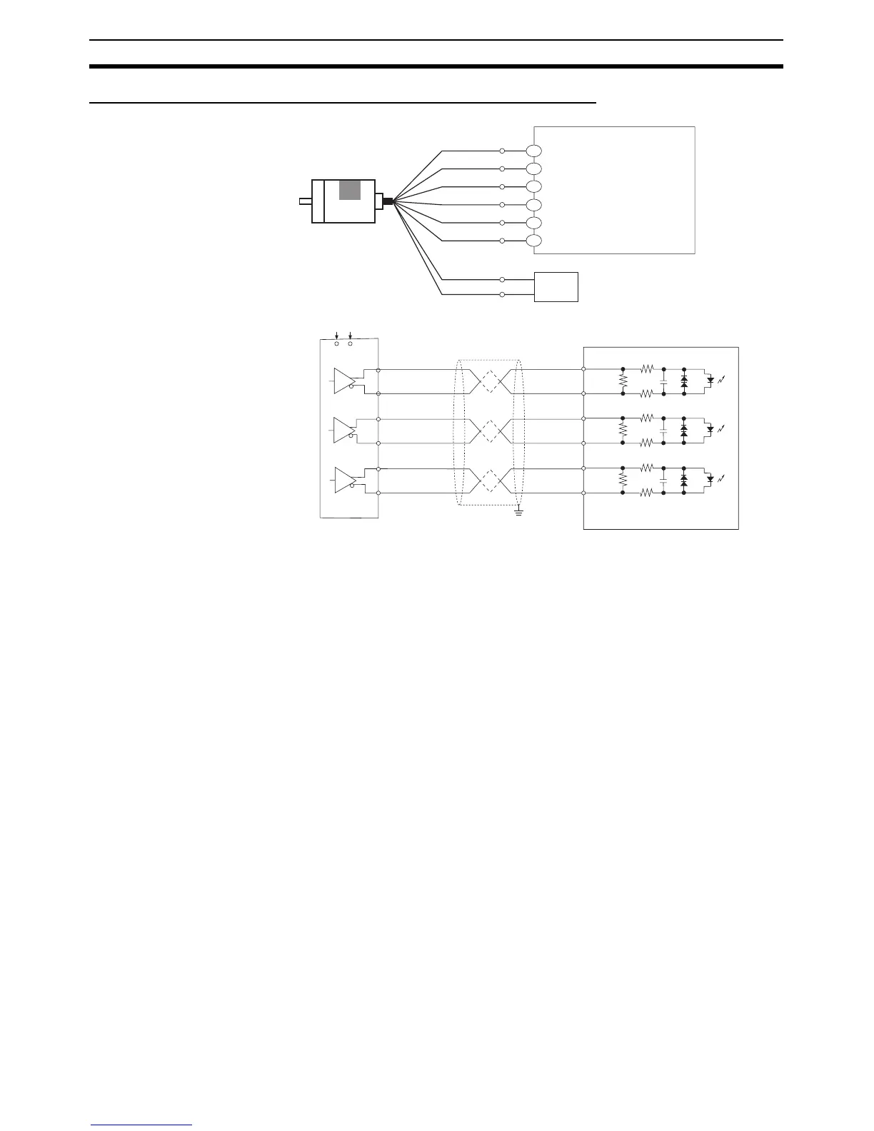
Encoders with Line Driver Outputs (Conforming to Am26LS31)
5-2-7 Ladder Program Example
Inspecting a Dimension by
Counting Pulse Inputs
• An X CP1H CPU Unit with an AC power supply is used.
• High-speed counter 0 is used.
• When the edge of the workpiece is detected, the counter PV is reset by a
phase-Z pulse.
• The workpiece is passes inspection if the final count is between 30,000
and 30,300, otherwise the workpiece fails.
• If the workpiece passes, output CIO 100.00 is turned ON by an interrupt
and the indicator PL1 is lit. If the workpiece fails, output CIO 100.01 is
turned ON by an interrupt and indicator PL2 is lit.
• The interrupt program is interrupt task 10.
(Differential phase input mode)
Encoder
Example: E6B2-CWZ1X
(line-driver output)
A+
Black
B+
White
Z+
Orange
5 VDC
Brown
0 V
Blue
A−
Black
(stripped)
B−
White
(stripped)
Z−
Orange
(stripped)
5-VDC power supply
+5 V
0 V
Y CPU Unit
(High-speed counter 0: Phase A, LD+)
(High-speed counter 0: Phase A, LD-)
(High-speed counter 0: Phase B, LD+)
(High-speed counter 0: Phase B, LD-)
(High-speed counter 0: Phase Z, LD+)
(High-speed counter 0: Phase Z, LD-)
A0+
A0-
B0+
B0-
Z0+
Z0-
A0+
A0−
B0+
B0−
Z0+
Z0−
Encoder
Power supply
Shielded twisted-pair cable
Z
−
Z+
B+
A+
B
−
A
−
CPU Unit

 Loading...


