384
Failure Diagnosis Functions Section 6-7
Auxiliary Area Flags and Words
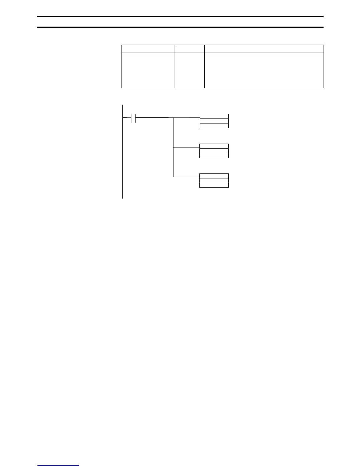
Example for a Battery Error
Note Use the same methods as for actual system errors to clear the simulated sys-
tem errors. Refer to the 11-2 Troubleshooting for details. All system errors
simulated with FAL(006) and FALS(007) can be cleared by cycling the power
supply.
6-7-4 Output OFF Bit
As an emergency measure when an error occurs, all outputs from Output
Units can be turned OFF by turning ON the Output OFF Bit (A500.15). The
operating mode will remain in RUN or MONITOR mode, but all outputs will be
turned OFF.
Note Normally (when IOM Hold Bit = OFF), all outputs from Output Units are turned
OFF when the operating mode is changed from RUN/MONITOR mode to
PROGRAM mode. The Output OFF Bit can be used to turn OFF all outputs
without switching to PROGRAM mode.
Application Precaution for
DeviceNet
When the CPM1A-DRT21 is used, all slave outputs will be turned OFF, i.e., all
inputs to the master will be OFF.
Name Address Operation
FAL/FALS Number
for System Error
Simulation
A529 Set a dummy FAL/FALS number to use to simu-
late a system error.
0001 to 01FF hex: FAL/FALS numbers 1 to 511
0000 or 0200 to FFFF hex: No FAL/FALS number
for system error simulation.
MOV
&100
A529
a
MOV
#00F7
D10
FAL
100
D10
Execution condition
Set FAL number 100 in A529.
Set error code for battery error
(#00F7) in D10.
Generate a battery error using FAL
number 100.