164
Auxiliary Area (A) Section 4-11
area). These words cannot be specified as instruction operands in the user
program.
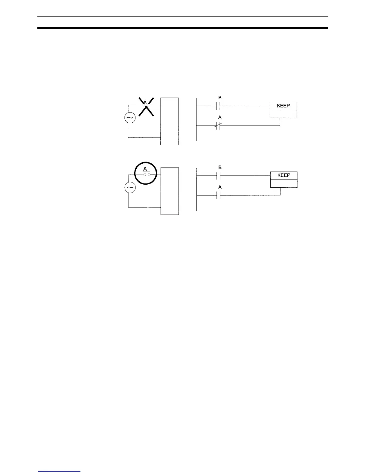
Precautions When a Holding Area bit is used in a KEEP(011) instruction, never use a nor-
mally closed condition for the reset input if the input device uses an AC power
supply. When the power supply goes OFF or is temporarily interrupted, the
input will go OFF before the PLC’s internal power supply and the Holding Area
bit will be reset.
Instead, use a configuration like the one shown below.
There are no restrictions in the order of using bit address or in the number of
N.C. or N.O. conditions that can be programmed.
4-11 Auxiliary Area (A)
The Auxiliary Area contains 960 words with addresses ranging from A0 to
A959). These words are preassigned as flags and control bits to monitor and
control operation.
A0 through A447 are read-only, but A448 through A959 can be read or written
from the program or the CX-Programmer.
Refer to Appendix C Auxiliary Area Allocations by Function and Appendix D
Auxiliary Area Allocations by Address for Auxiliary Area functions.
Forcing Bit Status Read/write bits in the Auxiliary Area cannot be force-set and force-reset con-
tinuously.
4-12 TR (Temporary Relay) Area
The TR Area contains 16 bits with addresses ranging from TR0 to TR15.
These temporarily store the ON/OFF status of an instruction block for branch-
ing and are used only with mnemonics. TR bits are useful when there are sev-
eral output branches and interlocks cannot be used.
The TR bits can be used as many times as required and in any order required
as long as the same TR bit is not used twice in the same instruction block.
TR bits can be used only with the OUT and LD instructions. OUT instructions
(OUT TR0 to OUT TR15) store the ON OFF status of a branch point and LD
instructions recall the stored ON OFF status of the branch point.
Forcing Bit Status TR bits cannot be changed from the CX-Programmer.
Input
Unit
Set input
Reset input
H1.00
Input
Unit
Set input
Reset input
H1.00